|
|
| Home > Articles > German > Jagdpanzer IV L/70 (V) - Guderian Enten |
|
|
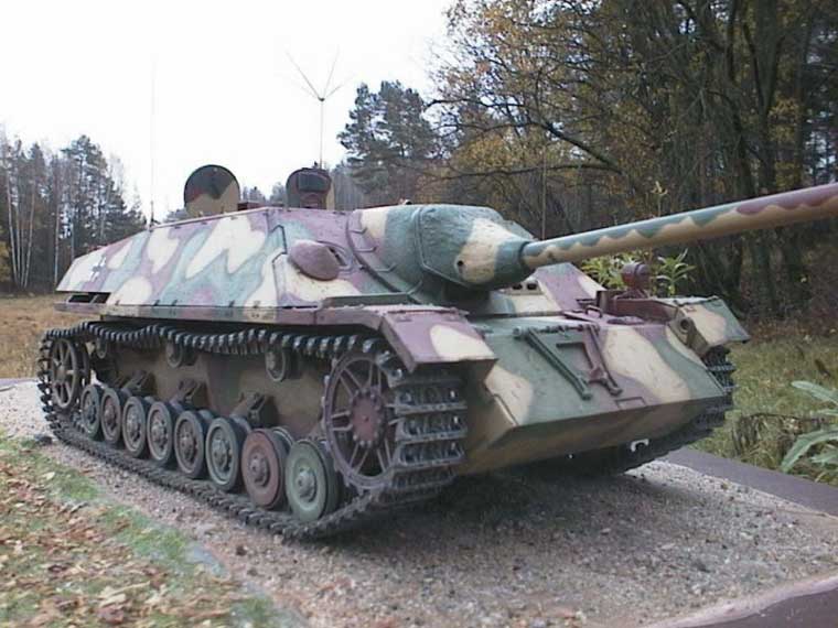
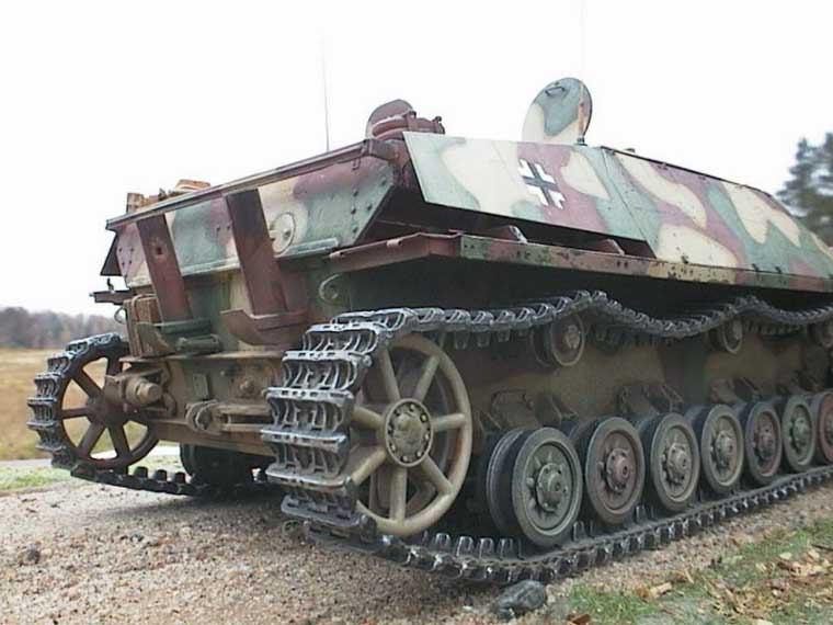
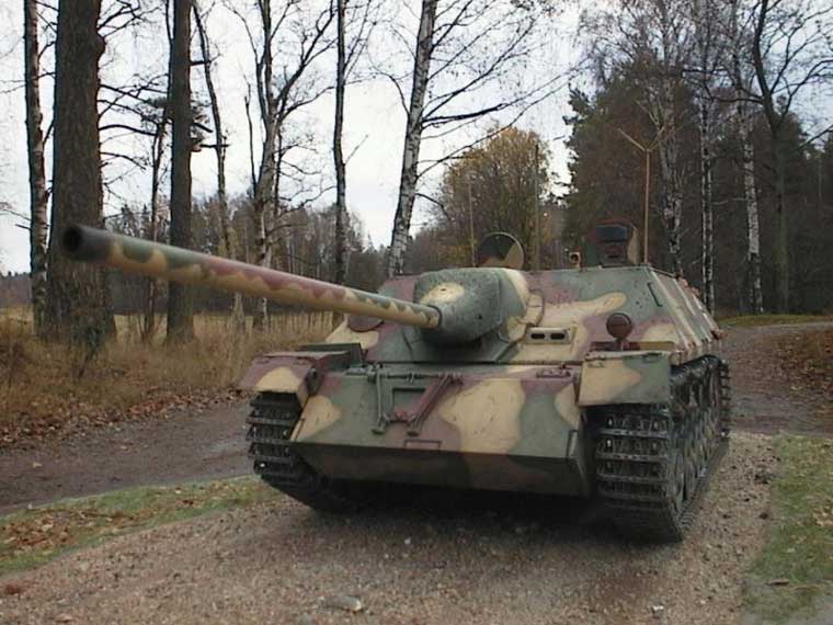
Jagdpanzer IV was a design initially opposed by General Guderian, the Inspector of the German Armored Forces from 1943 onwards. He did not see any point in producing a vehicle that to him was no different from Sturmgeschütz III or IV. However, his opinion was disregarded because Hitler liked the new design and especially the prospect of arming it with the effective 75 mm L/70 gun used in the Panther. Later on when Panzerjäger IV had proved its mettle Guderian was recorded saying that he would any day take three Jagdpanzer IV instead of two Panthers. This is also one explanation to the nickname of the tank that has stuck ever since: Guderian Enten. This can be loosely translated as "Guderian Hoax".
The model depicts a command version of Jagdpanzer IV L/70 (V) fitted with two radio sets, Fu 5 and Fu 8. In some command tanks Fu 8 may have been replaced with Fu 7 that was used for communication between Luftwaffe and armored units. In other respects the tank hunter is very much a standard issue. As these tanks were used in bigger numbers in Hungary in the winter and spring of 1945 I decided after consulting with Mr Bayerl that SS-Pz.Jg Abt 12 of the 12th SS Division should be an appropriate unit for my Jagdpanzer. Early on in the project I decided to build a full interior into this remarkably well stream lined Jagdpanzer. Later on I had plenty of time to regret this.
The kit is based on Gunzes Panzer IV chassis and the old high tech kit. All resin, etched or white metal parts of the original Gunze kit have been replaced with Dragons injection parts from their other Panzer IV kits. All in all the kit is a good starting point for the project because there are no major flaws to correct. Detail is a bit soft at places but the plastic used is not quite as soft as in some other Dragon kits. As this kit was packed in Gunzes box I wonder if the plastic was different than in the standard Dragon kits? The separate fighting compartment roof of the kit was an additional bonus because I needed to leave the roof loose in order to be able to display the interior.
Surprisingly it turned out to be a difficult task to find out what actually was within the Jagdpanzer IV fighting compartment. At least three museum vehicles of this tank exist but unfortunately none of them have an original interior. A further complication was my decision to build a command version. There was no information on where the extra radio set was in a command tank. From literature I could only find out that the command version had a 5-man crew instead of the usual 4. Consultation with some experts on the issue cast some doubts to this information and I decided to drop the 5th crewmembers seat. If anyone can tell me where the extra crewmember was positioned I would be more than grate full. I would like to take the opportunity to thank Mr Tony Greenland who kindly let me take copies of his shots of Panzerjäger IVs photographed in different museums. Without his kind help this project would not have been possible.
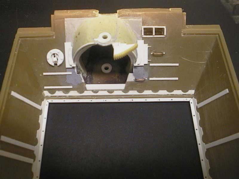
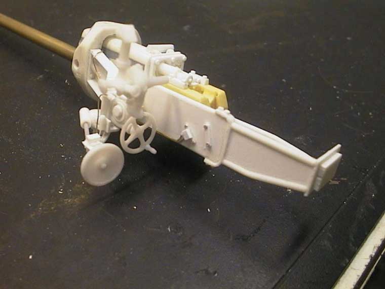
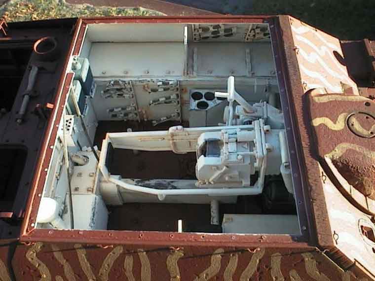
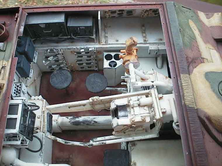
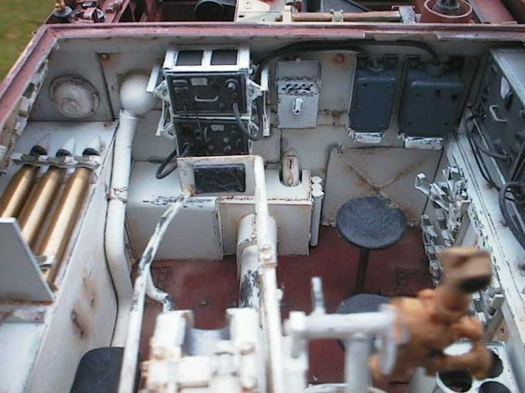
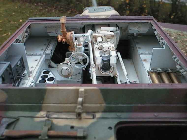
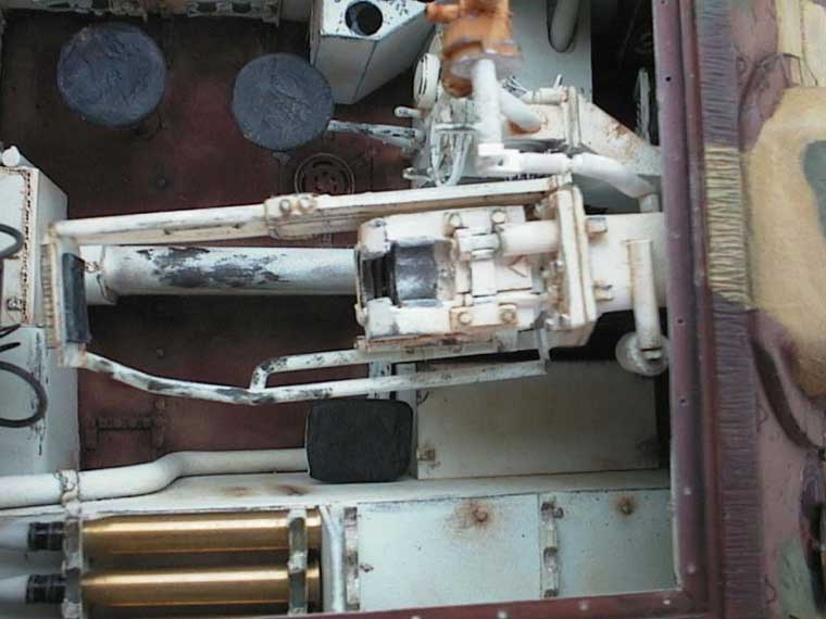
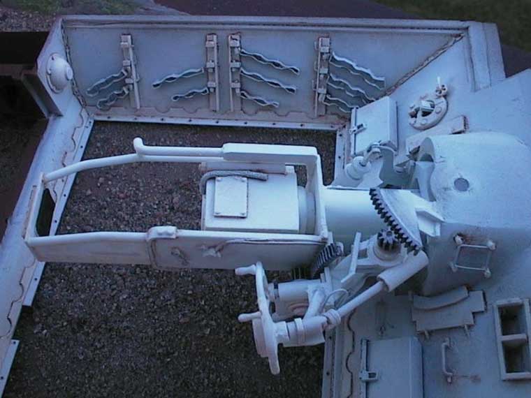
I started building the interior from the gun and its mount. As a reference I used Walter J. Spielbergers book Leichte Jadgpanzer and the photos received from Tony. With hindsight I should have done the mount as a separate drop in piece, just like the real thing. Unfortunately I chose to be clever instead. I glued the armored mounting (kit part) of the gun in its place on the frontal armor. Then I greased a small soft rubber ball and placed it inside of the mounting. The semi circular bottom part of the gun mount was then formed on top of the ball from Milliput putty. When the putty had cured I cut the edge straight and removed the ball. Actually it was easier said than done because the grease made the ball very hard to grab. Next a piece of 1.0*1.0 mm plastic strip was glued into the edge of the part made of Milliput together with a small semicircular plate with a hole in it for the yokes vertical axle. In order to position the hinge plate correctly a 2 mm hole was drilled through the top of the armored mounting. The interior and the exterior of the mount were then handled with wet and dry paper in order to make the contours smooth. Finally the mount was painted with Mr Surfacer 1000 in order to fix any remaining defects in the surface. The next part to make was the yoke for the gun. It was made out of pieces of 4 mm and 2 mm plastic card glued together. A hole for the gun was drilled and carved in the middle of the piece and then the yoke was cut to size with a saw and finalized with a hobby knife. A hole for the horizontal gun axel was drilled through the yoke. When both the mount and yoke were ready it was time to build the gun.Gun tube of the kit was no good as it was too small in diameter. Unfortunately the same applied to all after market sets that were available to me. The only way out was to turn a new barrel out of brass tube in a lathe. The correct measures could be found from one of Walter J. Spielbergers books. When the barrel was ready the breach block was taken from a Jaguar Panther interior kit. The recuperators were made from two pieces of 4.0 mm plastic tube that were glued on top of a piece of 6 mm plastic tube that formed the cradle. The cradle was drilled so that the brass barrel fitted into it. The cradle and recuperators were then wrapped into a rectangular piece made of 0.25 mm plastic card and an interior armored splash shield made out of 1 mm plastic card was added into the back end of the cradle. Next trunnions for the horizontal gun axle were glued on both sides of the cradle. The cradle was fitted into the yoke and a 2 mm hole was drilled right through. Then the breach block was glued into place and the recuperator rods were made out of 1 mm and 0.6 mm plastic rods. The securing nuts were made with a punch and die set out of 0.5 mm plastic card. The shield protecting the crew from the recoil of the gun was then built from plastic rod and plastic card, detailed and glued on. The circular interior mantle provided with the kit was also glued in its place around the base of the gun tube. Hand wheels of the gun were taken from the spare part box. Because they looked so good I made a mould out of them and cast some new ones out of resin for future use. At the same time I made a couple of castings of a gear wheel taken from an old clock that were needed for the gun traversing gear. I also made and cast a new sight, as the kit part could not be used. The traversing gear was made from plastic strips, plastic rod and excess pieces of plastic card. The most problematic part was fitting the gears so that they would look like they were interleaved but would still allow the gun move both side ways and up and down.When all the gun parts were ready it was time to fit the gun into the mount. Easy job because all the parts had been test fitted a zillion times. WRONG! The problem was that now that the cardanic axels were in place I could not get the gun into its place any more. The gun was too long to be turned into the right angle and thus it was impossible to get the yoke into the mount. This was again one of those days when one wished that one had chosen an other hobby. Luckily for me I did not have to start making a new gun or mount. I could make the opening in the frontal armor a bit larger. After this the opening was not exactly right shape any more but it was close enough. I would have avoided all this trouble if I had built the parts just like the German engineers did. I wonder if they encountered the same problem as I did when they tested with their wooden mockups?
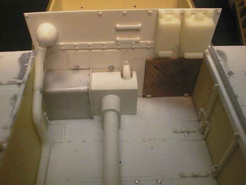
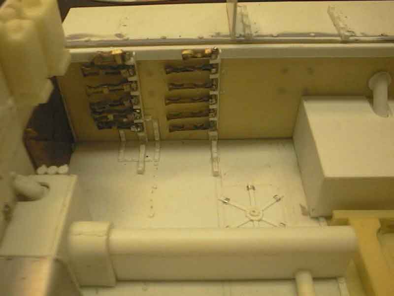
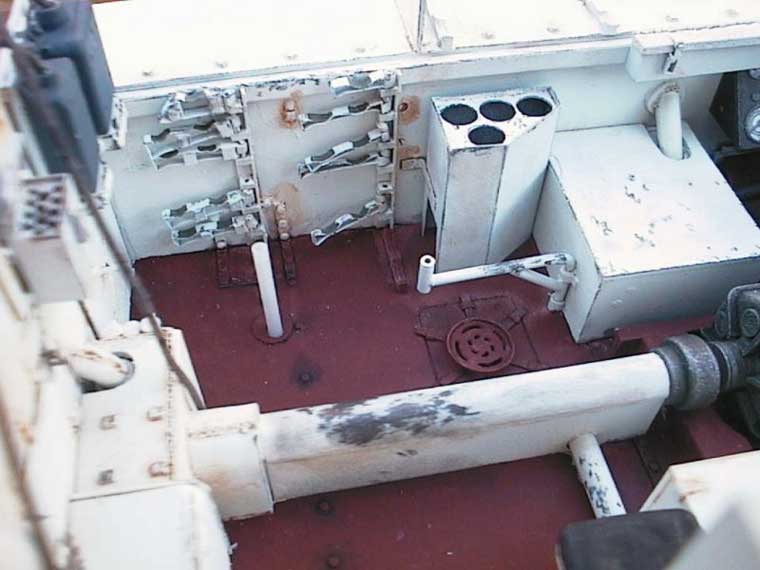
The trickiest parts to make in the interior were the ammunition holders. In the L/70 version they were made out of steel strips that were pressed into form. The scale thickness of the strip was about 0.2 mm and width 1 mm. After trying unsuccessfully to make a jig for pressing the parts I decided to etch them. I made some sketches on the ammunition arrangements on top of the sponsons in order to calculate the correct position of the ammunition on the racks. Three rounds lay on top of the sponson, three on the first rack, and two in the next and further two on the third. There were two racks to hold the ammunitions on each layer, one at the base and one at the shoulder of the cartridge. After making the measurements I drew the parts in Designer and made the films. Then I etched the parts and started to bend them into form. I had etched the racks thinner at the points were the ammunition were supposed to lay and tried to press the semi circular ammunition positions to them with a jig and a 3 mm drill. This worked fine but when I test fitted the racks the shell mounts were not in the same position in different layers of the racks. Thus the shells either did not fit into the racks or they were not correctly aligned compared to the sponson. The racks with ammunition also proved too high to fit into the fighting compartment. In order for the reader to appreciate the problem better: the height of the fighting compartment above the sponson is 17 mm, sponson depth is 15 mm, a shell is 3 mm in diameter and the minimum thickness of the rack is 0.4 mm. This means that the tolerances are calculated in hundredths of a millimeter. To make a long story very short: after 15 new drawings and films the problem had not gone away. Finally I dropped the idea of placing ammunition in the racks and conceded defeat. I decided to put the racks in up position into the fighting compartment walls. For anyone intending to build a Jagdpanzer IV with interior I recommend the short-barreled version. Its ammunition racks were made of wood and are far simpler to make with an accurate machine drill. Still, I think the racks look very good in the finished model even if the ammunition would not fit them. But please, keep the secret!
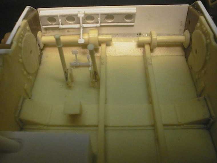
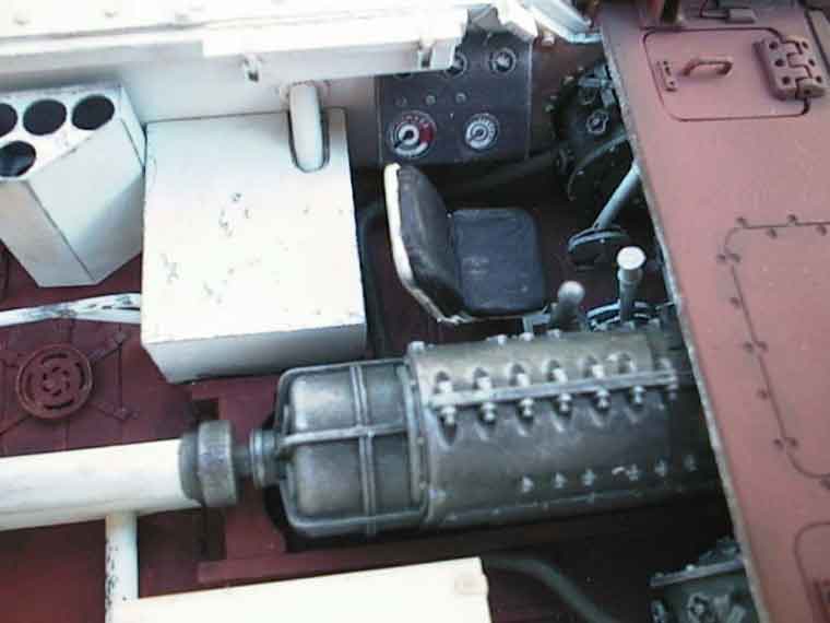
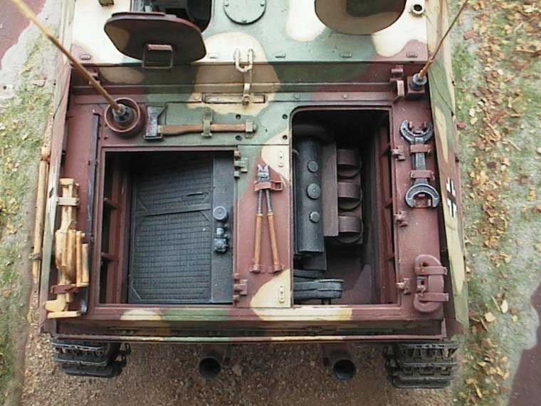
Most of the rest of the interior was pretty straightforward. The transmission housing came from Gunze Sangyos Panzer IV G interior set (if I were to do this again I would use CMKs excellent resin part) that received a new gearshift lever. Steering brakes came also from the Gunze kit but they needed some detailing because I decided to leave the left service hatch open. The required detail was made out of plastic strips according to a photo in Nuts&Bolts Wirbelwind -book. Sidewalls and the fire wall at the back of the fighting compartment were made of 0.5 mm plastic card and detailed with plastic strips, rivets and screw heads as shown in my photos. Fuel tanks and drive shaft tunnel were made of plastic card as well. Plastic tube was used for the smoke exhaustion pipes coming from the steering brakes. Seats were either scratch built or taken from the Gunze set above. At the same time with the ammunition racks I had also drawn the ammunition box with four rounds storage capacity that can be found beside the gunner. Rack for the radio and various storage boxes were also drawn and etched. These were then assembled and glued to place. The radios that I used are originally from MR Models radio set. Unfortunately my set had some nasty tiny air bubbles in almost all the radios so I had to fix them before they could be used. Wiring for the radios was made out of 0.2 mm copper wire and 0.7 mm round rubber band. The rubber band was taken from some old clothes that had a stretch band in the waist. Its excellent stuff for thick electrical cables and hydraulic tubes.
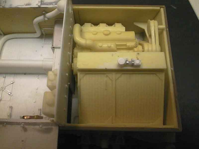
The engine compartment parts are mainly from the Gunze interior set. The engine and cooler are pretty well detailed. One only needs to add a couple of tubes connecting the cooler and the engine. Electrical wiring is placed so in the Maybach engine that it is almost impossible to see it from the open hatches so I left it out. Exhaust pipes were added as the rear part of them extending to the engine compartment back wall was missing. The big to Panzer IV characteristic fans were also well made but the axel connecting them was probably too thick. However, I chose not to correct the axle because I was not sure if it was protected with a metal sleeve when the vehicle left the factory. With hindsight I should have replaced the axel with a one made out of metal rod.
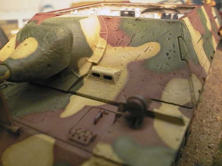
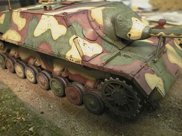
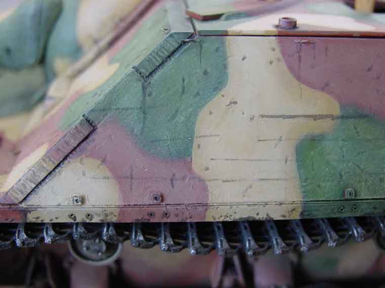
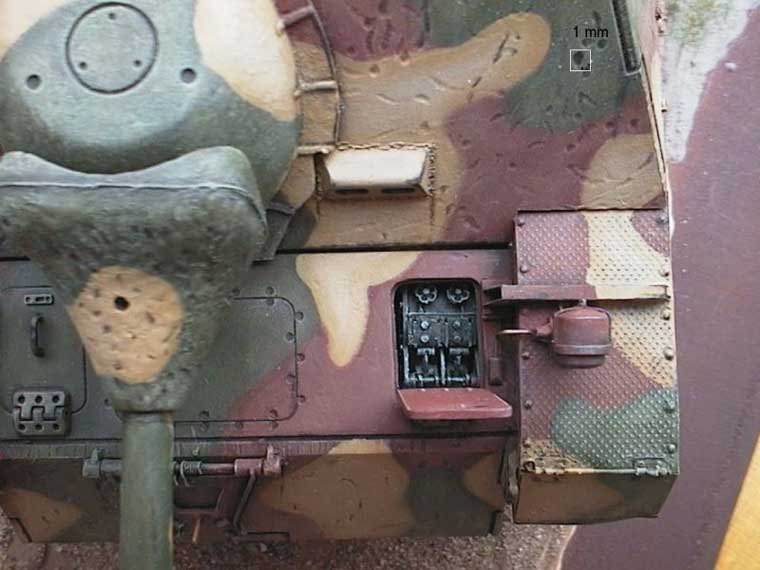
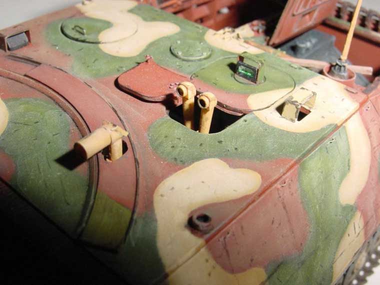
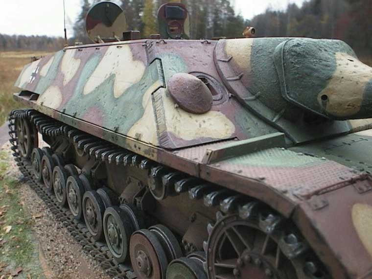
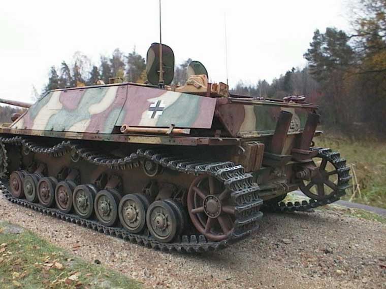
The biggest change to the exterior was the mudguards. I used Abers old Panzer IV mudguard set but replaced the textured plate in them with my own etched parts. This was done because the pattern in the Aber plates is not correct for Panzerjäger IV. There were no fit problems worth mentioning and the metal mudguards look much more realistic than the plastic ones. Just do not assemble them too nice! In the real tank they were always a bit bent, plates were not flush against the frame and so on.Most of the other detail came from the Aber etched set for Panzerjäger IV L/48. Only recently did Aber release a set for L/70, but I have not seen it yet. The L/48 set is not as good as some of the newer Aber sets but it has most of the stuff needed like the tool clamps and rear side armor plates. Although the tool clamps are a bit over size I like them. In my opinion the scale becomes an issue only if there is not enough room for the clamp at some particular place in the model. If there is room the fine detail of the clamps overweigh the size problems as the attached photos hopefully prove. The tools used in the model come mainly from Tamiyas Panzer IV accessory set.The rail of the armor plate that closes the opening for the sight on the fighting compartment roof was changed during the production of Jagdpanzer IV. Instead of being rounded like in my model it was constructed from short metal pieces screwed into the roof in most Jagdpanzer IV L/70. However, the only picture that I could find showing the roof of a command version of Jagdpanzer IV L/70 seemed to sport the initial version of the roof with rounded rail. Was there a shortage of parts at the factory? Gunzes road wheels are pretty good but the wheel hubs leave a lot to desire. Luckily I had some spares from the Model Kasten Panzer IV road wheel set. This set comes with three different types of hubs. One set of these extra hubs was used to replace the kits original wheel hubs. Tracks are from Model Kasten. Even if the kits own link to link tracks are good I prefer using Modelkastens or Friulmodellissimos tracks because of the natural sag that they produce between the return rollers. The detail of tracks from both manufacturers above is excellent and the assortment covers every model of Panzer IV tracks.The armoured mount and the external mantlet (Saukopfblende) were covered with a thin layer of Mr Surfacer. When the putty started to cure I made the cast pattern to it with a brush. I also made some marks and scratches to the surface of the front and side armor plates with a Dremel-tool. I am the first to admit that the quality of the German armor plate was very good and that in general the plates were very smooth without much texture or scratches. However, the scratches give life to the surface as long as they are not too dominant. In the attached photos some of the marks certainly look big but that is mainly because of the magnifying effect of the digital camera lens and file compression system. If you want proof of this please take a look at the picture with a scale attached to it.
Painting Interior of the vehicle was painted white before the hull halves were glued together. Floor was painted with red primer (brick red). I also painted the gearbox and break drums dark green and the seats matt black. Places where paint was likely to be worn off were painted with dark gray or pencil. 2B pencil is good for making chip marks because the graphite color has a metallic shine to it. The draw back is that it can stain also unintended places if one is not careful with it. In the end the interior received a wash with very thin red brown oil color. At first I painted the exterior of the model primer red with yellow vertical stripes as shown in the color plates of the Russian booklet about the battles around lake Balaton in Hungary in 1945. I had only 5 days to paint the model before the year 2000 Euro Militaire show and this scheme looked unusual to say the least and it was also easy to make in a short time. However, after the Euro Militaire I removed the paint from the model, because I could not find any evidence that such a scheme had actually existed. A very typical camouflage pattern for late Jagdpanzers was a factory applied three-tone hard-edged scheme that featured green and red brown over dark yellow base. Some good pictures of this paint scheme can be found for example from Walter J. Spielbergers book Leichte Jagdpanzer. In the Balaton book there are also many pictures showing a similar camouflage pattern although most of the pictures are of mediocre quality at best. After stripping the old paint I sprayed the whole model with Testors Rust color. When the base had dried I drew the camouflage pattern to the surface with a pencil. Then I sprayed the green and dark yellow areas on top of the base. This order contradicts to the order in which the colors were painted on the real tanks but the order does not really make a big difference. Less than 1/3 of the yellow base is visible in the finished product so it is more economical to use red brown as a base.
Airbrush naturally leaves the borders of the colors blurry. In order to make the camouflages lines sharper I dry brushed the border of each color with a darker shade of the color in question. Then I went on dry brushing all colors with a gloss shade. This gives a slight metallic appearance to the model. After dry brushing with the gloss color I left the paint to dry for a couple of days. It is essential that the gloss paint is absolutely dry before the process continues because otherwise also all the consecutive rounds will produce gloss surface and that is not the idea.I continued dry brushing with 3 or 4 different tones of green, red brown and dark yellow. It does not really matter what the tones are as long as you remember that the color should be lighter in the middle and darker in the border areas. When I was happy with the result I gave the model a very light wash with dark gray in order to give some depth to the detail. Note that I only applied the wash around detail not to the whole model.When the wash was dry it was time to make some scratches and chipping effects to the surface with diluted dark gray and black paint. A small brush was used to "chip" some paint from the mudguards and other sensitive places. As my model represents a tank that has hardly seen any major action there was no need to make extensive damage to the paint surface either. Just some modest marks here and there. White German crosses were painted to the side rear armor plates with a stencil. They were then filled with black using a small brush.
Wheel, tracks and lower hull were sprayed over with Humbrols dark earth color. When the color was dry wheels and tracks received a wash with diluted black. Then the wheels were dry brushed with a mixture of white oil paint and Humbrols dark earth enamel. I tend to spray the model with acrylics and use enamels mixed with oils for dry brushing. This prevents the different layers of paint mixing with each other a problem mentioned for example by Tony Greenland when mixing dark earth with white oil color. Finally the rubber rims of the wheels were painted black and the track, drive sprockets and idler were dry brushed with oily steel color and Tamiyas silver pen. Last touch to the model was a wash with thinned Tamiya buff. The paint was thinned in 1: 20 ratio, one drop of paint to 20 drops of Tamiya thinner. The wash was applied with a large brush that ensured that no brush marks would be left to the surface. When the wash had dried water stains were added with very thin black around the tie downs on the sides, gun mantle, tool clamps on the sides, holes in the mudguards etc.
Conclusion Jagdpanzer IV L/70 (V) is one of the most elegant looking German armored vehicles from WWII era. Gunze Sangyos (DMLs) Jagpdanzer kit is a very nice reproduction of this remarkable vehicle and it builds into a very nice looking tank hunter without any major modifications. It also offers a very good starting point to anyone wanting to build a vehicle with full interior. There are basically no problems with the major dimensions and the way the kit is designed leave all possibilities open. The only place where cutting is needed is the frontal armor that does not have a right shape hole for the gun. I really enjoyed building this model apart of the small difficulties with the ammunition holders of course!
DML, Jagdpanzer IV (V) L/70 Command Version, kit #9043 Model Kasten, Pzkpfw IV Road wheel set, kit # W-2Model Kasten, Final Model (light weight) track for Panzer IV, kit # SK-27Gunze Sangyo, Super detail interior/engine for Pzkpfw IV Ausf. G, kit # G-794Aber, Jagdpanzer IV L/48 set, 35037
Nuts&Bolts vol 13, Flakpanzer IV Wirbelwind (sdkfz 161/4) & OstwindWalter J. Spielberger, Hilary L. Doyle, Thomas Jentz: Leichte Jagdpanzer, isbn 3-613-01428-9 Hilary L. Doyle, Walter J. Spielberger, Armin L. Sohns: Bellona Military Vehicle Prints 30AFV Interiors page at http://www.kithobbyist.com/AFVInteriors/jgpz4/jgpz4a.html |
| |
|
Home |