Converting Academy's Mid Tiger #1387 into a Mid or Late Tiger with an
Accurate Interior
by Matt Messmer
 Introduction
Academy's early Tiger I has been called, by some, one of the best Tiger
kits on the market. I have built their early Tiger, and it was nice, but
it had many problems. All were correctable though. Still, I was hoping
that many or all of these problems would be corrected in the mid. They
were not.During the Tiger's production history it underwent many changes
to both the exterior and interior of the tank. These changes are broken
up into three, four depending on who you ask, classifications: the initial,
early, mid, and late production Tiger I. The changes were very gradual,
though. It is hard to tell a late mid from an early late, for instance.I
had heard of the problems with the mid Tiger kit, how Academy had really
cut some corners and included many of the early kit's parts. However,
the kit is actually the early Tiger with a few new pieces included to
convert it into a mid. This includes the later version cast commander's
cupola, new parts for the later version Maybach 230 engine, single headlight
on the driver's front plate, and so forth. They forgot, however, the interior
of the tank. The kit still retains the early version interior, which was
inadequate for the early kit and now is compounded by the fact that the
mid Tiger had a vastly different interior. Unfortunately, very few, if
any, of the problems experienced in the early kit have been fixed, such
as the lack of struts running on the hull floor, inaccurate interior details,
incorrect turret, and so on.It is my hope that this article will help
you build an accurate Tiger I, inside and out, mid or late. In this article
you will find the dates of all of the production changes made, from July
1943, the general starting point of the mid Tigers, though the end of
production, to the Tiger I series. These dates will be accompanied by
detailed instructions on how to build the missing parts or correct the
existing ones.
Research
Finding information about the exterior of a late Tiger is relatively easy,
as it is well documented in many books. Information about the interior,
and more importantly pictures and diagrams, is more difficult. I found
one web site that provided much of my reference material, Tiger1e.com.
This site supplied many of the important diagrams and explanations on
the workings of the Tiger. It even has walk through of the late Tiger
at the Saumur panzer museum. If you like books, too, "Germany's Tiger
Tanks D.W to Tiger I" by Thomas Jentz and Hilary Doyle will be right
up your alley. It has many well-made scale drawings, some original German
plans, and goes through every part of the Tiger piece by piece.
The Building Process
Before we start, I would like to make the following notes. First, I will
try to follow the instructions as closely as possible, and I will tell
you when I am deviating from the order given in the instruction booklet.
Second, it can be assumed that when I do not mention any problems with
a given part (this won't be often) it can be installed as per the instructions.
These two things may seem rather obvious, but I wanted to include them
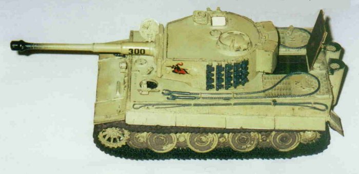
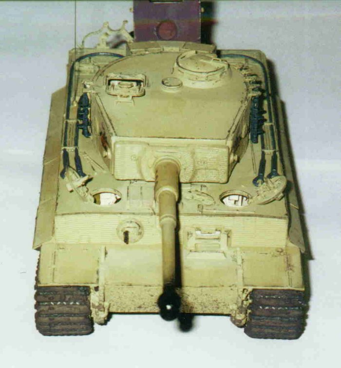
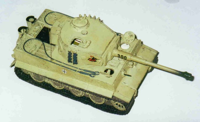
as to avoid confusion.The tank I will be modeling is a Tiger made in early
February 1944. This Tiger, Fgst. Nr. (Fgst. Nr. is short for Fahegest
Nummer, in English Hull Number) 250829 (The 829th Tiger made), was received,
along with six other replacement Tigers, on the 8th of April, 1944 by
the s.Pz.Abt.505. Upon arrival this particular Tiger was given to the
3rd company commander.As stated before, for those of you wishing to build
Tigers made before or after the one I will be modeling, I have included
the date and, if I can, the Hull Number (Fgst. Nr.) and Turret Number
(Turm Nr.) with which the changes were made. Since Academy makes an early
Tiger, and this article is dealing with their mid Tiger, I will list only
the changes made after July 1943, the general turning point from early
to mid. So, unless otherwise noted, when I refer to all Tigers, I am speaking
only of those made after July 1943.For those building Academy's early
Tiger, this article can help you as well. Many basic problems of the mid
kit are those left over from the early. Much of the work done to the lower
hull and hull fighting compartment should be done to all makes of Tigers.
The time specific detail work described in this article will be inaccurate
naturally. For the most part only the work done in step 3 "The Lower
Hull" and step 6 "The Hull Exterior" will be accurate.
I suggest that those building the early kit refer to John Prigent's excellent
article on building Academy's early Tiger, also on this website.Well let's
begin!
Step 1: The Wheels
The first thing we will do is assemble the road wheels ,drive sprocket,
and idler wheels.
1.1 Road Wheels
The kit comes with the early model rubber rimmed road wheels found on
earlies and mids. Starting after Fgst. Nr. 250822, in February 1944, the
steel rimmed road wheels made for Tiger IIs were mounted on Tiger Is.
The road wheels I have used came from a late Tamiya Tiger that I had laying
around. The wheels where the same kind installed on Tiger IIs and very
late Panthers. If your Tiger was built before this date, there is no problem.
Just be sure to put the wheels on with the insides facing in. Because,
the inside face of the wheels have numbers molded on that should not be
there.
1.2 Idler Wheel
The Tiger also had two different types of idler wheels. The kit, however,
only comes with the larger early type. For those building Tigers made
after late February 1944 you will have to go to the aftermarket. Model
Kasten makes the later idler wheel for about $15.
Step 2: The Rear Plate
A few things need to be changed to the rear plate. (I am lumping steps
four and six together, it is clearer in writing this way)
2.1 Feifel Air Cleaners
On most Tigers, the holes for the Feifel air cleaner system will need
to be filled with putty. This system was not mounted on Tigers built after
October 1943. Be sure to remember to remove the molded location lines
on the hull top. For those building a mid Tiger, due to the parts being
stockpiled, some Tigers built as late as December 1943 still had the brackets
for the Feifel air cleaner brackets on the hull. These comprise of four
screws, two on each side. In the kit, these are molded onto the Feifel
air cleaners. (A good picture of these screws can be seen on Panzer Colors
III p.57, bottom of the picture in top left corner)
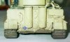
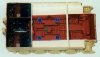
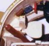
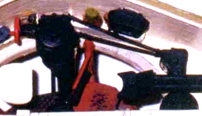
2.2 Kuhlwasserhiezgerat
Next is the Kuhlwasserhiezgerat, or the motor coolant heater. This was
installed starting with Fgst. Nr. 250823, in February 1944. It had a blowtorch
access port on the lower port side of the rear plate. When not in use,
the port was covered by an oval shaped cover secured by two bolts, one
on each side. The kit does not include this and it must be scratchbuilt.
Start by making the oval shaped mount. This piece is 3mm tall and 4mm
wide. It should be made from 2mm thick plastic sheet. Then place a bolt
on the left side and another on the right. This cover had a small blunt
point coming out of it. To make this, get some 2mm wide plastic tube and
mark off a section of the tube 2mm from the top. Next, using some sandpaper,
sand the tube at a 45-degree angle until you reach the line you drew earlier.
What you should have is a blunt point on the end of the tube. Cut the
tube at the drawn line and mount it in the center of the oval cover. See
photograph above for further reference.
2.3 C-Clamp
The kit comes with the C-Clamps mounted on Tigers completed after September
1943. The instructions show it as being mounted lower than it actually
was. The bottom of the clamp should be level with the bottom of the mount
for the left rear fender.
2.4 Track Toolbox
For those of you building Tigers made before November 1943, you will need
to put on the track toolbox, piece D15. This goes directly above the left
rear fender. In fact you can see the locating pin molded onto the rear
plate. This pin must be taken off, of course, if your Tiger does not have
the toolbox.
2.5 The Jack
Lastly is the jack. The kit comes with the 20t jack mounted on Tigers
after Fgst. Nr. 250772, built in January 1944. Because of the nature of
the kit, it also comes with the materials to build the 15t jack mounted
on earlier Tigers. This is very simple, just substitute piece D12 for
L12.
Step 3: The Lower Hull
Now we move on to the construction of the interior in the lower hull,
kit steps five and parts of seven. In kit step number seven the instructions
tell us to put in the firewall, engine compartment, the driver's seat,
and the radio operator's seat. This should be postponed indefinitely.All
of the work that is to be done in this step should be done to all Tigers,
no matter when produced.
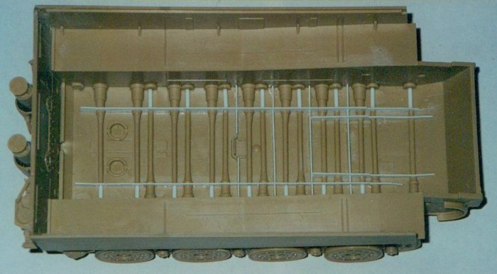
3.1 Struts Along the Hull Floor
The first thing that must be done to the interior, before any of the
torsion bars are installed, is to build the missing struts that ran across
the floor. The struts were mounted throughout the Tiger's production history,
even earlies. This diagram from Tiger1e.com
shows a good overall view of the struts and where they go relative to
each other
3.1.1 Longitudinal Struts
The longitudinal struts, the two largest struts run from the rear
to the front of the tank. We will need to make these from the smallest
width plastic strip we can find, as the real struts were only 10mm thick.
The strip I am using for all of these small things is 0.5mm. The real
struts were 200mm tall. In 1/35 this is about 6mm. Because the kit has
the torsion bars mounted on the floor, they were in reality not touching
the floor, of course, the struts need to be shorter. I found that plastic
strip 4mm tall was the best. Any taller and the struts appeared to be
too tall. The starboard side strut must be at least 100mm long, the port
110mm. You might want to go a bit longer just in case. The strut on the
starboard side stops just short of the front torsion bar. The port strut
goes all the way to the front of the hull. This brings them up to the
firewall. Anything on the floor past the firewall can't be seen because
of the large engine.Now we should place the struts in the lower hull.
The lower hull comes with the beginnings of the torsion bars already molded.
This works out well for us, because where the molded part ends is exactly
where the torsion bars went through the struts. The molded torsion bar
parts have locating pins that need removal for the struts to fit snugly.
There are two more longitudinal struts over the first five torsion bars
that need to be modeled. These struts should be made from the same 4mm
plastic strip cut to 47mm long. They should be placed 4mm to the center
of the tank from the other longitudinal struts.
3.1.2 Transverse Struts
The Tiger also had four struts running across the hull. These transverse
struts run between every two torsion bars, starting from the third bar
on back to the tenth. The real ones ran between holes in the longitudinal
struts. Our struts will not go through the longitudinal struts, but will
be built around the longitudinal struts in three parts, two end pieces
and a middle piece. Before we continue, remove the two bulges in the center
of the hull. I did not do this, as I did not realize they should not be
there before it was too late. All of the transverse struts should be modeled
from 0.5mm plastic strip cut to 3mm high. The eight end pieces are 4mm
long, and the three middle pieces are 30mm long. The front most strut
crosses all four of the longitudinal struts, so it will need a special
middle piece. First insert all of the end pieces. They should be placed
between the tenth and ninth strut, the eight and seventh strut, and so
forth. The middle piece, for the last three struts, should be placed now.
They should line up with the end struts, of course. Now, the front strut's
middle piece. Start by cutting two 3mm high by 4mm long pieces of 0.5mm
plastic strip. Insert them between the longer longitudinal strut and the
shorter longitudinal strut. Then, with the same plastic strip, cut a 21mm
long section of strip to form the middle piece.
3.2 Torsion Bars
Once all the struts are tightly in place, the torsion bars can be mounted.
We will model the back eleven torsion bars first. The front five, like
the front transverse strut, must be made to fit around all four longitudinal
struts.
3.2.1 The Back Eleven Bars
Start by cutting down eleven of the kit's torsion bars to 30mm. You
should cut off the end with the large cylinder bulge and discard it. These
30mm pieces, like the transverse struts' middle pieces, are placed between
the two longitudinal struts. This brings the torsion bars only part of
the way across
the hull. The remaining part should be scratchbuilt from 1.7mm plastic
rod.
3.2.2 The Front Five Bars
Now for the front five torsion bars. Use the remaining five kit bars and
cut them down to 4mm. Don't discard the rest though. This small piece
should be placed between the long longitudinal strut and the short one,
next to the molded torsion bar. It should look just like the beginnings
of the other eleven bars. Now with the remaining torsion bar piece, cut
a 21mm long section, again not using the large bulge. This is placed between
the two shorter longitudinal struts. Then with a 1.7mm plastic rod, cut
a 4mm piece to be placed between the other long and short longitudinal
struts. The remaining part of the torsion bar can be made with the same
1.7 plastic rod.
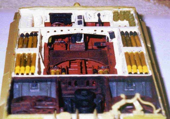
3.3 Color of the Hull Interior
The kit instructions say to paint the lower hull in a green-gray color.
This would be fine for an early, but after late 1942, the German high
command sent out an order that everything that was painted green-gray
before was to be left in the red oxide primer. Not only the hulls, but
the equipment too. (Due too stockpiling of parts, however, some vehicles
made soon after the color change still had some equipment painted in green-gray)
The boundary for the color was the top of the sponsons. Everything below
this line was red primer. The only exception, in the hull, was the engine
compartment. This was left completely in primer. Everything above this,
until the turret, was painted in a light beige.The paints I have used
are as follows: The red primer is a Polly Scale color called "Ital.
Camo Red 2." The beige color is a Model Master Acrylic called "Panzer
Interior Buff" also available in enamel.
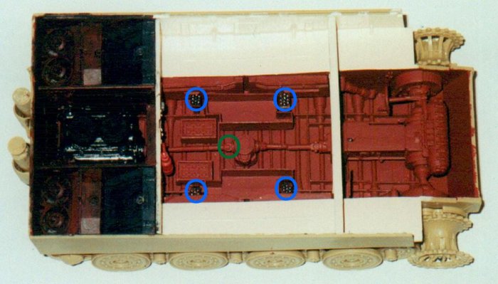
3.4 Lubrication Points
Now it's time for some scratchbuilding. First are the lubrication points.
The kit omits these. They were mounted throughout the Tiger’s production.
These four points are mounted on pillars, between the seventh and eighth
torsion bars and between the eleventh and twelfth torsion bars. All of
the pillars were painted in red primer but would become very greasy. All
of the lubrication points had ten small-unpainted rivets on them where
tubes attached. I put on the rivets but not the tubes, as they can't be
seen.
3.4.1 Front Lubrication Points
Let's start with the front two. Take a strip of plastic card, 4mm
wide and 0.5mm thick, and cut off two pieces, both 17mm long. Bend these
pieces at a 90-degree angle where they're 11mm high. These should be mounted
between the sixth and seventh torsion bars, on the port side of the starboard
longitudinal strut and the starboard side of the port longitudinal strut.
3.4.2 Back Lubrication Points
The back two were much different. To model these, cut a 5mm piece
of our handy 4mm wide and 0.5mm thick plastic strip. Attach this 2mm from
the top, to a pillar 2mm wide, 0.5mm thick, and 13mm high. These were
mounted between the eleventh and twelfth torsion bars, this time on the
starboard side of the starboard longitudinal strut and the port side of
the port longitudinal strut.
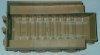
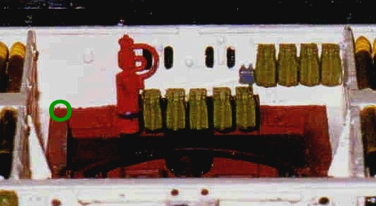
3.5 Under Turret Bins
Next are the missing bins under the turret floor. There were two bins.
Each held six shells, two facing forward and four back. The bins were
open-topped, and the rounds were held in place by two straps. The shape
of the bins is very odd. The front two shells are 22cm ahead of the back
four. They were made like this to allow them to sit astride the batteries
and the lubrication points. A good diagram can be found here on Tiger1e.com.Well let's
start. Both of the bins should be made from 0.5mm plastic strip, all cut
7mm high. The two longest sides should be 27mm long. As said before, the
two front rounds were 22cm in front of the back six, so these walls are
6mm long. The side with the two rounds has ends on it 4mm long. The back
six rounds have walls 7mm long. The bins should be painted in the red
primer color like the rest of the lower hull. They should be placed 5mm
away from the wall, glued to the longitudinal strut. We will need to purchase
some extra shells because the kit only supplies those need in the main
ammunition bins (to be modeled later). These are not hard to come by.
Tank Workshop, Tamiya, and Verlinden make them to name a few. Be sure
to get enough, for we will need more later when we get to the main ammunition
bins, twelve extra in all.The instructions tell us to paint the shell
caps incorrectly. Part A12 should have a yellow grenade with a black cap.
Part A13 should have a black grenade with a white cap.
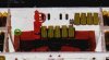
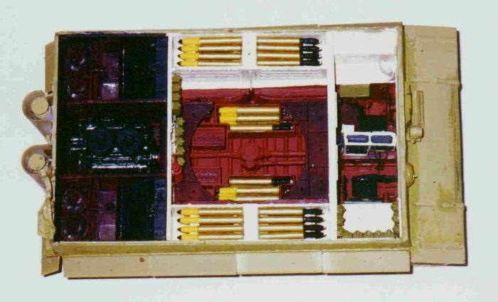
3.6 Batteries
Now we should do the batteries. The kit has the batteries mounted
at the same position. They were in reality tapered. Both should be placed
close to the ammo bins, the starboard battery 3mm away from the back of
the bin, and the port one 1mm away. For further help see the pictures
further on in the text.
3.7 Roof Brace
The kit tells us to put in the roof brace at step 12. I will be using
his as a reference point for other items so it should be put in now. The
kit has it in the wrong position. It should be mounted behind the back
location line on the sponson top. Just remove the front one.
3.8 Shocks
The last thing we must do to the lower hull interior is modify the shocks.
The kit shocks are both mounted in the wrong position. We should start
by removing the molded location lines for the shocks. While we are at
it, remove the location lines for the radio operator's seat support, starboard
side by the shock's location lines.The port shock should be mounted onto
the third torsion bar and sloped back until it is over the fourth torsion
bar, a few millimeters away from the roof brace. For the starboard shock
we must do more work. The kit has the shock sloping back like the port
one. It should be facing forward. Cut off the part of the shock that mounts
to the torsion bar. Glue this to the opposite side of the shock. It should
look identical to the port one. Mount this to the second torsion bar sloping
forward until it is 27mm away from the front of the tank
Step 4: The Engine Compartment
Again I am lumping some steps together. The kit instructions tell
us to jump around. To me this is confusing. If you want to do it their
way, here is the order: the changes to the firewall and building of the
cooling fans' gearboxes should be made at step seven, before the engine
is built and inserted. Then we jump to the building and installation of
the engine in steps eight and eleven. Then on to step twelve where we
build and insert the fuel tanks, radiators, and cooling fans.
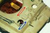
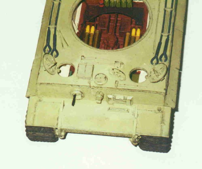
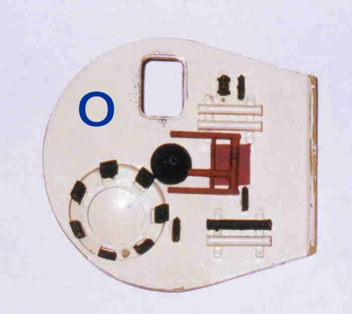
4.1 The Firewall
Starting after Fgst. Nr. 250501 in September 1943, the firewall was
redesigned and many of the components mounted on it were moved. Some of
the things on the firewall need to be cut away. They are hard to explain,
so refer to the picture above to see how it should look. Next, for those
building a Tiger constructed after Fgst. Nr. 250861 in February 1944,
a small fuse box should be mounted in the lower left corner of the firewall.
This is a jumble of wires coming out of the engine compartment with a
small light gray box. Also, a rack for MG ammunition need to be built,
this can be made from a strip of plastic .5mm thick, 1mm wide, 25mm long.
Onto this ammunition bags are attached.
4.2 The Fan Drive's Gearbox
When the new Maybach 230 engine replaced the 210, the gearbox for
the cooling fans was changed. In fact another gearbox was added (for a
more detailed explanation of the gearboxes see Tiger1e.com) I could not
find any plans for the gearboxes where measurements where given. So I
have had to eyeball the dimensions of them.
4.2.1 Port Side Gearbox
We will start with the fan on the port side. In the back of the engine
compartment, you can see a large circle on each side. This has a series
of bolts around it and other small openings nearby. This larger circle
is where we should start. Cut a 10mm long piece of 4mm wide plastic tube.
Attach to this a 6mm long 2mm wide tube 2mm from one end. It should be
at a 45-degree angle. To the upper right of our large circle, you can
see a small oval mount with two bolts on either side. Attach the top of
the 2mm wide tube to the small oval mount. Then attach to the larger circle
the side of the 4mm wide tube to which the 2mm tube is connected. If you
are going to have the engine out of the compartment, you will have to
do some more work to this gearbox. Since the engine hides the bottom part
I have not bothered with it.
4.2.2 Starboard Side Gearbox
The starboard side gearbox is much the same as the port side gearbox.
We should cut another piece of 4mm wide plastic tube to 10mm long. Attach
to the top of this a piece of 2mm wide plastic tube. The variation here
is that it is bent downwards in the middle.
4.3 The Engine
Now for the engine. The kit comes with the parts to make a Maybach
210 engine. This engine was mounted on Tigers before Fgst. Nr. 250251
in May 1943. After this, a new engine, the Maybach 230, was mounted in
Tigers. The main external difference is the change from three air filters
to two. The air filters supplied in the kit are much too shallow. We need
to enlarge them. Start by cutting 5mm off the bottom of the engine. You
will also have to take out the last three torsion bars. They can not be
seen anyway. Then cut out two 5mm pieces of plastic strip in the same
size as the air filters.The kit engine, with the air filter fix, is passable
but not completely accurate. All the work needed on the engine to make
it, from my view, look correct is not worth the time or the effort. So,
I opted for a Tank Workshop Maybach 230 engine. At $10 it seemed the most
accurate, and almost as importantly the easiest, thing to do.
4.4 The Fuel Tanks
For these the kit parts are fine for Tigers built before Fgst. Nr.
251075. For these Tigers the fuel tanks were unpainted metal. This was
a very dark metallic gray steel like what was used for the armor.Tigers
built after Fgst. Nr. 251075, in April 1944, had wooden strips placed
on the fuel tanks. To represent these strips, a 1mm thick piece of plastic
card should be placed on the tanks and textured and painted as wood.
4.5 The Radiators
The radiators come with grills on both sides. This is fine and accurate,
but they also have bolts sticking out. On the side where the cooling fans
will be mounted, these should be cut off so the fans can fit flush with
the radiators. Again a note about color. The radiators should be painted
red primer, but the small cap on top was black.
4.6 The Cooling Fans
If you put the cooling fans in as they are in the kit, they are too
low in the hull. We will need to move them up a bit. Make sure that the
glue used on the radiators is dry, otherwise they will slide. Then insert
the fans. The large circle, where the gearboxes were placed, should be
completely covered by the fans. The kit leaves it exposed. The fan drives,
like the fuel tanks, are unpainted metal.
Step 5: The Fighting Compartment
Now the fun begins, scratchbuilding, moving parts, and correcting kit
mistakes oh my. All of the work done in this step should be done to all
Tigers.
5.1 The Transmission
The kit transmission can be built as is. The paint scheme shown in
the instruction book is very odd. The transmission should be painted in
red primer.
5.1.1 The Radio
Attached to the transmission is the radio. This should be painted dark
gray, but the frame that it sits in, molded onto the radio kit piece,
should be painted the interior light beige color. There should also be
a grouping of wires coming out of the radio. Just take some copper wire
and model them coming out of the radio and down the side of the transmission,
where they will disappear under the floor (to be modeled later.)
5.2 The Tower Unit That Supplies Power to the Turret
Now one of the major mistakes of the kit. The turret in the kit is centered
over a gap between the ninth and tenth torsion bars. It should be directly
over the ninth bar. This is a difference of 4mm, so on the real thing
14cm. While this may sound like a hard problem to fix, but it is not.
All we must do is move the tower unit that supplies power to the turret
and move the hull roof so the turret can be farther forward. We should
not worry about the roof yet. One problem at a time. The tower is held
over the torsion bar by two strips running between the transverse struts.
These should be made from 0.5mm thick plastic strip, cut to 1mm wide and
10mm long. These should be placed between the transverse struts, one by
the starboard ammo bin, the other 4mm to port from the center of the vehicle.
Then mount the tower onto the port strip, centered in the hull over the
ninth torsion bar. Now attach the two kit parts, F17 and G5, that connect
the tower unit and the transmission. They will need to be cut down by
3mm then glued into the tower and transmission. Next, attach the part
that connects the tower to the engine, part F17. Cut off the end of it
that attaches to the engine. Then a piece of 1.7mm plastic rod, cut to
fill the gap, should be mounted between the two ends. Then attach it to
the tower and engine.
5.3 Ammunition BinsOnward to the ammunition bins. We will first
model the bins along the hull sides. These, kit parts G31-G34, are a bit
under sized. All of them should be 30mm long. The kit's bins are two sizes,
23mm long and 28mm long.We will start with the smallest bins, parts G34
and G33. Start with a piece of plastic card 7mm long and 12mm tall and
1mm wide. Attach this piece to the side of the bin. Now we must make the
ends of the bins. Cut a 2mm piece of the same 12mm tall and 1mm wide plastic
card. Attach this to the inside of the previous piece.Now for the longer
bins, kit parts G31 and G32. For these bins we only need a piece 2mm long.
The end should be attached in the same way as the last bins.The lids of
the four bins should be the same. Take a strip of plastic 27mm long 3mm
wide and 1mm thick. An angle should be cut 4mm from the front of the lids
to match that of the bins. Attach these lids to the tops of the bins.
The lids should match up with the backs and the sides of the bins. The
front has a small bulge coming out that is not covered by the lids.All
of the bins have two strips running across the sides of them. These are
0.5mm by 0.5mm, and are molded onto the kit bins. We should continue the
strips that were molded on the kit parts. Next, the mounts for the floor
plates need to be cut down a bit. Dry fit the panels, parts G14 and G15,
to see how much needs to be cut off. None of the mounting should show.
The outside of the bins should be painted in red primer. The inside was
beige.The back two bins should be mounted 1mm from the top of the sponsons
flush against the firewall. The front two should be mounted at the same
height 2mm away from the back two. They should be 1-2mm from the roof
brace. The gap between the two should be centered, more or less, over
the ninth torsion bar.
5.4 The Floor Plates
Now we will install the floor plates. For these the kit parts are fine,
but a few things need to be added. First the circles in the panels need
to be drilled out. These are finger holes to lift off individual panels.
Under these panels were some bins for storage. These were under the left
and right panels of both plates, for four total.Lets start with the front
ones first. The bins are 14mm long by 12mm wide and are 7mm deep. The
width of the plastic does not mater because it is hidden by the other
floor panels. Mount the bins under the front left and right panels. Be
sure to leave room for the floor plates to fit onto the supports molded
to the ammo bins. The whole assembly should be painted red primer, but
the floor panels would become very dirty. Next, place the panels on the
supports. Slide them back to the front of the roof brace. They should
cover part of the transmission.The back two bins are much smaller. They
are only 10mm long by 8mm wide and are 7mm deep. They should be mounted
under the left and right plate, again making sure there is enough room
for the floor plate to fit on the mounts. Now place the floor plate in
position. The bins should sit between the firewall and the rear lubrication
points.
5.5 Driver's Compartment

Next we move forward to the driver’s compartment. Not much to be
done here.The first thing we should do is build the floor panel behind
the driver. This has a very complex shape. A very good diagram can be
seen here on Tiger1e.com.
The basic shape is 12mm long by 16mm wide. There are two cuts in the plate
so that it can fit around various items coming out of the hull floor.
One, in the forward port corner, is 2mm long by 5mm wide. This should
allow it to clear the port shock. The other in the forward starboard corner
is 5mm long by 2mm wide. This plate should be mounted onto the port storage
bin, the one under the other floor plates, and should come up to the third
torsion bar. Onto this plate a gas mask should be placed. The kit comes
with these parts, A19. Put one of them next to the hull wall, under the
torsion bar.Now insert the driver's seat, from kit step 7 in the instructions.
The seat should be placed back far enough that it comes up to the front
of the floor plate. The seat cushions were black leather. The frame was
painted red primer.Moving up we find the driver’s ammunition bin,
part G26. This is a bit too small. This is because of the roof brace being
too far forward. A small piece of plastic card 4mm wide and 14mm long
should be glued along the curve of the bin. Glue this piece to the front,
the side that is open.The gyroscope, part H18, should be moved forward
in the hull. This must be done to make sure it clears the ammo bin.
5.5.1 Driver's Front Plate
As we swing over to the radio operator’s side of the hull, we
should assemble the inside of the driver's front plate. This is in kit
step 14. Nothing must be added that is not in the instructions but the
vision port for the driver should be painted black. Don't glue this to
the exterior part yet.
5.6 Radio Operator’s Compartment
Next it’s over to the radio operator’s compartment. Again, not
very many things must be done here.First we have more floor plate work
to do. Cut off the mounting from the side of the radio operator’s
seat. Then add a 15mm wide by 6mm long piece of plastic strip to the radio
operator’s seat. You will have to cut down the sides of the plate
to which the seat is molded so it is not too wide. Mount this to the under
floor bin 4mm away from the side of the hull. The radio operator’s
seat was black leather. The plate was painted red primer. There should
also be some bins and such along the wall next to the seat. First is a
spare barrel case for the machine gun. This should be made from a piece
of 1.5mm plastic rod, cut to 16mm long. Mount the case above the gunner’s
seat. Above this is another gas mask. Also, there is a box for a spare
glass vision block. This can be made from a small square of thick plastic
strip. Refer to photos for placement.
5.7 Roof Brace
Now we move back to the roof brace. This was already put in at step 5,
but a few things are missing.On the starboard side, the large opening
should be filled with plastic card. Then get some of the kit’s ammo
bags, parts E4, and put them around the front side of the roof brace and
the adjacent wall. Next are three small boxes mounted on the bow side
of the starboard half and the bow and aft sides of the port half. The
boxes were all the same size, 1mm thick, 3mm wide, and 5mm tall. These
boxes should be mounted 2mm from the top of the roof brace and 15mm from
the wall. On the aft side of the starboard half there was a small gearbox
instead of a storage box. The gearbox is the same size as the other boxes,
exept it is tilted at the same angle as the edge of the roof brace. This
box had five wires coming out of it. Two of the wires came out the bottom.
The other three came out the top of the gearbox and went though the most
starboard of the small holes in the roof brace. All of the wires ran down
the edge of the roof brace in a hollow conduit.Lastly two Atemschlauch
breathing tubes need to be put on the roof brace. These should be made
from 1.5mm thick plastic tube cut to 15mm long. There are ten small holes
in the roof brace. The tubes should cover three of these each, leaving
the end one exposed.
5.8 Main Ammunition Bins

Now we must do some work to the main ammunition bins. The kit bins only
hold three shells. The real ones held four. This requires some minor corrections
to the bins.
5.8.1 The Starboard Bin
The first thing we will build is the wall that separates the aft facing
ammunition and the bow facing ammunition. Take a strip of 1mm thick plastic
card and cut it to 14mm by 6mm. To one side mount a 14mm by 14mm square
of plastic. This will be the bow side. To the other side mount a 15mm
by 14mm piece. This will be the aft side. The two pieces must be a different
height because of the angle in the sponson floor. To support the shells
we must add a small strip, 14mm by 3mm, to each side of the wall 5mm from
the top. Next, take piece G2 and mount our newly built wall where part
F25 would go, discard part F25. Now we need to build a replacement part
for piece F27. The dimensions of our part can be the same, 14mm by 3mm.
5.8.2 The Port Bin
Before the starboard bin is installed we should build the port bin. Both
bins were identical, but because the port side of the roof brace has a
large opening in it, all three racks of the bow facing shells can be seen.
This requires us to fill this empty space. Instead of mounting just one
14mm by 3mm to the dividing wall we must add three, all 5mm apart from
the last. The same must be done for the F27 replacement part. Eight rounds
must be purchased because the kit only comes with enough for the top racks.
We should have some extras left over from the under turret bins.
5.8.3 Installation of the Bins
Both bins should be centered in line with the ninth torsion bar, in
the gap between the smaller ammunition bins. A small strip, about 1mm
long, should be placed between the outer bin wall and the firewall. There
should not be a gap between them. Another strip should be placed between
the outer bin wall and the roof brace. This one should be about 2mm long,
and shorter than the bin so it can fit under the lip of the roof brace.
The last thing we will do to the bins is put on a piece that runs down
the center of them. Start with a strip of plastic card 1mm thick, 18mm
long, and 4mm wide. Make a cut, 6mm by 3mm, in one of the corners, this
will be the bottom right hand side. On the side of the strip that is still
18mm long, the left-hand side, make a mark 6mm from the bottom. In the
top right hand corner make a mark 1mm to the center, left, of the strip.
Now cut from one mark to the other. You should come out with a piece that
looks like an elongated number four. Make two of these pieces, one for
each bin. Mount one in the center of each the bin. The notch in the lower
corner should fit around the sponson.
Step 6: The Hull Exterior
The hull exterior is probably the easiest part of the whole building
process. Not a whole lot of scratchbuilding to do here, some but not much.
Lots of moving around kit parts, however. We will start with the front
of the tank and work our way back.
6.1 Front Hull
During this front hull section, I will be jumping around in the instructions
again. I will be covering parts of kit steps 11, 13, 14, and 26, and all
of step 15. The instruction book's layout is good for an early mid, if
you leave on the S-mines and headlights. For now leave off parts B8, B7,
and B9, the grills over the engine compartment.
6.1.1 The S-Mines and Headlights
The first thing the instructions tell us to do, in step 11, is remove
the S-Mines and the headlights from the upper hull plate. The number of
headlights was reduced from two to one in August 1943. If your Tiger was
built before August 1943, you should put on both headlights, parts E8
and E7. One can see the mounts on the kit. The instructions tell you to
remove them. For a short time after August 1943, a single headlight was
mounted in the left front of the driver's side. Starting with Fgst. Nr.
250570, in October 1943, the headlight was moved to the center of the
driver's front plate, where the instructions tell us to put it. If your
Tiger would not have had the center mounted headlight, you should substitute
piece B10 for piece K3.The S-Mine dischargers were mounted on mid Tigers
until early October 1943. These were mounted at the four corners of the
hull and halfway down the port side. The front two S-Mines and the one
halfway down the port side are parts E28. One can see the mounts on the
hull top. They are the two strips at the given position. The rear two
S-Mines are each made from two parts, E2 and A21. On part E21 there are
three triangles, one on the top and two on the bottom. The bottom two
triangles should be mounted diagonally on the corner of the hull. Then
put an A21 onto the top triangle. The S-Mine should point outwards, away
from the tank.
6.1.2 The External Equipment
The front part of the Tiger is where the majority of the external
equipment was stored. This equipment was moved to different locations
quite often during the production history of the Tiger. It would also
be moved during the normal wear and tear that the crew and combat would
put the tank through. Because of this, I can only write about the location
of the items when the tank left the factory.
6.1.2.1 Tigers before Fgst. Nr. 250850
For these Tigers we need only deviate slightly from the kit instructions.
Start by mounting parts D21, D18, and D36 in their given positions. If
your Tiger was made before the Fgst. Nr. 250496, in September 1943, then
leave off the C-Clamp, part L19. In addition, you should move parts D23,
D35, and D19 forward a few millimeters. Also, for Tigers built before
January 1944, put part D24 on the glacis plate. Part D14 should not be
mounted except to the earliest mids.
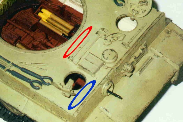
6.1.2.2 Tigers made after Fgst. Nr. 250850
Here we need to deviate considerably from the kit instructions. Start
by taking some 3mm by 3mm square rod. Cut a piece 17cm long. Starting
5mm away from the turret ring at the rear edge of the hull plate glue
this rod around in a curve. It should finish on the other side of the
turret ring lined up with where you started. This ring requires that some
of the equipment be moved. Parts D21, D36, D23, and D19 can be mounted
as shown in the instructions. Part D35 should be moved in front of the
radio operator's hatch. Part D18 should be mounted behind part D19.
6.2 The Rear Hull
We should start off the rear hull by installing pieces B8, B7, and
B9, as you may remember these were left off in step 6.1. When installing
them be sure to put a 3mm thick piece of plastic card between part B1
and parts B7 and B8. This is to move the gap for the turret over the ninth
torsion bar. The front of part D1 should be sanded down so that it can
fit. Again I am jumping around in the instruction book. This section will
cover steps 13, 14, 25, and 26.In kit step 14 we assemble the engine hatch
cover. Parts E29 and D30 should only be put on if your tank still has
the Feifel air filters. As said before, due to stockpiling of parts these
showed up on Tigers months after the system was dropped.As a small note,
the gun travel lock was mounted on Tigers built from Fgst. Nr. 250635
in November 1943 through Fgst. Nr. 250867 in February 1944. The kit includes
the parts to make this, located all the way back at step 25.On the very
rear of the tank, part B9, there is a small cap with an "X"
on it. This should be cut off and replaced by a thin triangle 4mm by 8mm
by 10mm.
6.3 The Tracks
The tracks that come with the kit are good for a laugh! The kit has
them advertised as "flexible one-piece tracks." The one-piece
part is right, but they are not flexible. Quite the contrary, they are
as stiff as vinyl plastic can be. They should be replaced or the model
might be ruined.You have a few options. If your Tiger is made before Fgst.
Nr. 250570 you will need to get the early model tracks without the ice
cleats. Many companies make these. If your Tiger is made after Fgst. Nr.
250570 you will need the late model tracks with the ice cleats. Again,
these are made by lots of companies and are priced from $20-$50.
6.4 Zimmerit
This rippled paste was applied in a rippled pattern staring in August
1943. I have made the mistake of using Cavalier Zimmerit. I do not recommend
this product unless it all you can get. My set had numerous air bubbles
in it that I had to redo. It also came with holes in the pattern where
it was smoothed out. I think these were supposed to be damaged spots but
they were not recessed. These to had to be cut out and redone. Don’t
be tempted by this easy solution to doing zimmerit. It is a double-edged
sword. I suggest getting a set of Tamiya zimmerit sculpting tools and
doing it yourself. In the instruction booklet there is a decent guide
that shows you which surfaces to apply the zimmerit to.
Step 7: The Turret Interior
In this step I will only cover turrets made after Turm Nr. 250392, mounted
on Fgst. Nr. 250391 built in July 1943. At this point the turret interior
was redesigned almost completely. So unless otherwise indicated all work
done in this step should be done to all mid (post July 1943) and late
Tigers. Some early mids did have the early version turret, ones that were
built in May and June 1943. If you are building one of these Tigers I
suggest that you buy or build a replacement roof for your Tiger (one with
the early version components) and refer to John Prigent's excellent article
on building Academy's early Tiger, also on this website.Here we will cover
steps 16, 17, 18, and 19 in the instruction book. The instructions will
not be used very much though. The kit comes with most of the parts for
an early turret interior, and much will be scratchbuilt.
7.1 Symmetrical Turret
Some of you may know that the turret of the Tiger I was asymmetrical.
This information did not surface until recently, and manufacturers are
just getting around to producing asymmetric Tiger turrets. Our kit has
the incorrect symetric turret. This can be fixed easily enough, Armoured
Brigade Models make replacement turrets for both mid and late Tigers.
For those who wish to make their own, Tiger1e.com provides the step-by-step
information to do that.
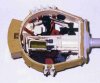
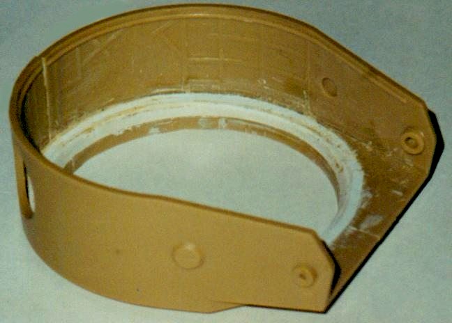
7.2 The Turret Ring
The interior section of the turret ring is far from accurate. Here on
Tiger1e.com, we can see a great cut-away of the turret ring.
As you can see the kit ring is too low in places and is not depicted correctly.
The whole thing should be at the same level as the chin area. Also, the
edge should be at an angle, not square as it is in the kit. I thought
long and hard about how to correct this problem. I thought of making the
replacement ring completely out of putty, but this is far beyond my sculpting
ability. Building the replacement ring completely out of plastic would
be too difficult, as the plastic would not bend at an angle and a curve.
I finally came up with a solution that incorporates both ideas. Unfortunately
it requires that both turret halves be glued together. This will limit
the area with which we have to work, but the turret is big enough that
we can pull it off. Start by cutting 19cm long piece of 3mm by 3mm square
plastic rod. Glue this to the inside of the turret along the ring. This
should make the whole ring the same level as the chin. As you can see
the plastic rod does not come all the way out to the edge of the ring,
this is where the putty comes in. The putty should be placed in the niche
and sculpted to the desired angle with a dull knife. Before this is done
be sure to sand away at the area where the two turret halves meet. They
are not at a curve like the rest of the ring. Also sand off all of the
location lines along the turret ring. These will not be needed.After this
is done paint the interior light beige.
7.3 The Turret Gearbox
The instructions for building this are in step 16 in the booklet. The
gunner's seat, parts J31 and J14, should be left off for now. The front
of the gearbox should be 38mm from the front of the turret. Next we should
install parts J36 and J18. As you can see in the earlier diagram from
Tiger1e.com part J18, the azimuth indicator, should be at an angle to
part J36. There should also be two rods, one 22mm long the other 24mm
long, that run between the turret gearbox and part J36.In early Tigers,
this assembly was painted black. Some time between then and Fgst. Nr.
251114, it was changed to ivory.
7.3.1 Adjacent Storage and Other Things
In front of the gearbox is one of the storage bins and a pillar that
suspended the turret floor. The pillar is made from a 1.5mm thick plastic
rod 28mm long. It should be glued to the turret ring in front of the gearbox
and bent around the ring and down the side. We will attach it to the floor
later when that is built. The storage bin should be made from 0.5mm thick
4mm high plastic strip cut to 23mm long. 3mm from each end make a 90-degree
bend in the strip. Place this 2mm in front of the pillar. It should go
just a little bit past where the turret walls stop curving. This bin,
and all the others, should be filled with assorted items that the crew
would have.
7.4 The Commander's Area
Start this step by making another bin. This time use a plastic
strip 21mm long, again the sides 3mm long. Place this bin on the rear
side of the turret gearbox. Make sure it curves with the turret ring.
At the end of the bin is the commander's seat.
7.4.1 The Commander's Seat
The kit seat is all wrong. The only part we can salvage is the backrest,
part F11. Start with a piece of 1.5mm thick rod cut 10mm long. On one
end mount a 1mm thick 3mm by 6mm strip of plastic. This end will be the
top. At the bottom of the strip attach on a 4mm by 4mm rhombus. This is
where the seat connects to the turret ring. Now, at the bottom of the
10mm long rod, glue on either side, two 1mm by 1mm square rods. That is
where the seat will attach. The seat should be made from a 1mm thick 10mm
by 10mm square of plastic card. The back half of the seat is a semi-circle.
The front corners are rounded. Unlike the early seat, this one did not
have a cushion. Finally, glue the seat onto the 1mm by 1mm rod and then
the whole assembly to the turret ring at the end of the storage bin.
7.4.2 The Pistol Port
The pistol port was installed on turrets before October 1943. The kit
includes the exterior portion of this, part K19. But like so many parts
of the kit the designers have forgotten the interior portion. The following
instructions only apply if the pistol port is plugged and not removed
for use.Start by making a water-droplet shaped plate. This will form the
plug for the port. The two straight sections of the droplet are 4mm long.
The semicircle at the bottom of the droplet is 5mm in diameter. It should
be 1mm thick. In the center of the semicircle glue a 1mm thick 2mm long
rod. Then glue the assembly on the inside of the turret, opposite where
part K19 is on the exterior. Next, to the left and down from the plug
glue another 1mm thick by 2mm long rod. It should be 3mm away from the
plug. Lastly, attach two small chains, one 9mm long the other 4mm, between
the two 1mm by 2mm rods.
7.5 The Counterbalance Cylinder
Next to the commander's seat is the counterbalance cylinder for the
gun. In the early tiger this was mounted laterally on the starboard side
of the turret. In the late turret is was redesigned and placed vertically
in a housing.
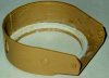
7.5.1 The Housing
First, we must build the housing in which the counterbalance cylinder
rested. This had a very odd shape. Here on Tiger1e.com,
we see a cut away diagram of the turret. It clearly shows the port side
of the housing and the counterbalance cylinder, labeled "Federausgleicher".
The starboard side was identical. As you can see the shape is hard to
describe. Although, now that you can see the shape, I can give some dimensions
so it can be modeled. The dimensions, in 1/35 scale, are as follows: On
the inner side, the one that curves, the straight part is 25mm long. The
outer side of the housing, that closest to the turret ring, is 24mm long.
The length of the side that is attached to the turret ring is 5mm long.
The side that is vertical is 7mm high. The two pieces are 4mm apart with
a wall in back separating the two sides. The housing should be glued to
the turret ring facing forward, not curving with the ring. The port side
should be 0.5mm away from the wall.
7.5.2 The Counterbalance Cylinder
Start by attaching a 2mm by 2mm box centered above the housing on
the turret wall. It should be placed under the lip where the roof is placed.
On the bottom of this box the counterbalance cylinder was attached. The
cylinder in the early kit is part J49, this can be used with one small
change. The triangular piece coming out the backside should be removed.
This end should be mounted on the bottom of the 2mm by 2mm box and draped
down through the housing.Next is the cam that attached the counterbalance
cylinder to the gun. It did so by means of a chain fixed to both the gun
and the cylinder. From the previous diagram it is hard to grasp the shape
of the cam. This photo, on Tiger1e.com,
of the late Tiger at the Saumur panzer museum, shows the relationship
between the cam and the other pieces.Start building the cam by cutting
a piece of plastic card to 1mm thick, 4mm wide, and 7mm long. Mount this
under the counterbalance cylinder facing outwards. To the front starboard
side of this we attach the cam. The cam should be made from a 32mm long
1mm wide by 1mm thick strip of plastic. For now imagine that one end of
the strip is glued to the front starboard side of the 1mm by 4mm by 7mm
piece. It should start out facing diagonally starboard and downwards.
Five millimeters from this end, straighten the strip so it faces forwards
again. Then at this same point, bend the strip upwards. Next, 7mm from
the last point, the strip should bend in a curve for 10mm. Then the strip
takes a sharp curve downwards, and then curves back for 6mm. Lastly, the
strip bends back to port where it connects to where it began. The piece
that is attached to the gun will be modeled later along with the chain.
7.6 The Bock and Brücke
These parts are missing from the kit altogether. They served as a
gearbox for the elevation mechanism on the gun and supported the loader's
and the gunner's seats. Before we build it though some more bins and a
few other items need to be constructed.
7.6.1 Bins and etc.
The first of three bins should be made from a 26mm long 4mm high strip
of plastic card. Again bend in the side at 3mm. It should be mounted directly
next to the counterbalance housing. To the right of the bin is the MP40,
piece J35. Then next to the MP40 is another floor supporting rod. It should
be made the same way as the other, from a 28mm long 1.5mm wide plastic
rod bent around the turret ring. The second bin comes on the other side
of the escape hatch. This is a long one, made out of plastic strip 36mm
long. On the outside of this bin is the locking system that kept the gun
from moving when engaged. This can be made very simply from a thin triangle
of plastic 8mm by 7mm by 7mm. Glue the 8mm side to the outside of the
bin, along the turret ring, 2mm away from the front edge. Then bend the
triangle downwards and glue it to the vertical side of the turret ring.
On the bottom point glue a hand-wheel 2mm in diameter.The last bin should
be placed 11mm ahead of the last. It is a short one. Use a plastic strip
16mm long.Lastly, the vision port, part J30, must be moved over 3mm. Move
the molded detail on the outside too.
7.6.2 The Bock
This is another item with a complex shape. It is hard to describe, although
like the counterbalance housing, I can give dimensions for it if you have
a diagram.
7.6.2.1 Dimensions
Let's start with the front side. This is the top diagram. The straight
part of the aft side, on the right, is 10mm long. Moving around clockwise,
the other section of the aft side is 6mm long. The bottom side is 3mm
long. The bottom bow section, bottom left, is 6mm. The vertical part of
the bow side is 8mm long. The top section is 8mm long.Now the top. This
is shown in the second diagram. As said before the side that connects
with the front face is 8mm long. Going around clockwise, the bow side
is 7mm long. The rear side is 7mm across. The aft side is 6mm long. As
you can see the aft side has a small section that is at a 90-degree angle
with the front side. It is 2mm long.Next are the sides. These are not
shown very well in the diagrams. The bow side only had a side wall on
the top. It did not have a wall running down the side. This can be faintly
seen in the top diagram. It can be made from plastic strip 7mm long 2mm
wide. The aft side had a wall going down the side too. This is 2mm wide
and 10mm long. The side section should be 2mm wide and 6mm long.The very
top vertical section of the Bock, shown in the top diagram, is the simplest
part. It is made from 1mm thick plastic card 10mm high and 9mm wide. It
should be placed in behind the other parts of the Bock. Also six should
be glued on, one in each in the corner and two, along the top and bottom
in the middle.The color of the bock changed when the turret was redesigned.
It should be ivory, not the light gray I have painted mine.
7.6.2.2 The Elevation Mechanism
This part of the Bock was not shown in the last diagram. For some
reason it was omitted. Start by attaching to the center of the Bock a
3mm long section of 4mm wide plastic tube. In the center of the tube glue
a 3mm piece of 2.5mm wide plastic tube. On the end of the last tube glue
a 2mm wide 6mm long and 2mm thick piece of plastic strip. Glue the strip
so that the forward edge is exposed and is level with the turret ring.
The forward side should come to a point at the end and should be rounded
in the back. This attaches to the gun. Of course, this will have to be
done latter when the gun is built.
7.6.2.3 The Loader's Seat
This seat attaches to the Bock on the aft side. The support should be
made from a 1.5mm thick plastic rod 23mm long. On one side glue part J6
this is the backrest. Glue this side to the Bock and then bend the remaining
part upwards. It should be at a 90-degree angle to the part attached to
the Bock. The seat frame is placed on this part. The seat is exactly the
same as the commander's seat, made from a 1mm thick 10mm by 10mm square
of plastic card. The back half is a semicircle. The front corners are
rounded.
7.6.3 The Brücke
The main part of the Brücke runs from the bottom of the Bock to the turret
ring on the opposite side. The last diagram shows the Brücke
decently. Start with a 2mm thick plastic rod 55mm long. At 42mm from one
end bend the rod upwards. Then 10mm from that, bend the rod back straight.
It should look like a large starter crank on an old car, or Tiger tank.
Glue the straight end onto the bottom of the Bock. Glue the other end
into the gap between the main gearbox and the first storage bin. The whole
thing should be painted red primer, except for the portion on the port
side where it comes up above the level of the turret bottom. This should
be painted ivory
7.6.3.1 Floor Support Rod
Attached to the Brücke were a number of items. The first one we will
model is the last floor support rod. Unlike the other two, this rod was
not welded onto the turret ring. It should be made from 1.5mm thick plastic
tube 13mm long. Glue it to the Brücke 2mm away from where it attached
to the Bock.
7.6.3.2 Another Gearbox
Next to the floor support rod was a gearbox. The kit comes with this
part, J27, as it was in the early Tiger next to the large hatch in the
rear of the turret. Glue this part 3mm away from the floor support rod.
It should be painted black. The gearbox had a wire running into the transverse
motor. This will be modeled when we get to the turret floor.
7.6.3.3 Control for Elevation Mechanism
Now we will model the gunner's control for the elevation mechanism.
This is a long pole coming out of the Bock and running above the Brücke.
Start building this by gluing a 2mm by 2mm box on the Bock 4mm above the
Brücke. Then glue a 1mm thick 23mm long piece of plastic rod on the square,
running above the Brücke as said before. One millimeter away from the
end glue a 1mm thick, 1mm wide, and 4mm long piece of square plastic rod
between the Brücke and the above tube. Finally, glue part J17 to the end
of the round tube.
7.6.3.4 The Gunner's Seat
Lastly is the gunner's seat. The seat itself is the same as all of
the other seats. The backrest is attached to a rod coming out of the Brücke.
Start by mounting the seat 5mm away from the 1mm by 1mm by 4mm rod that
was attached earlier. It should be near where the Brücke curves upwards.
For the back rest glue a 1mm thick 8mm long piece of plastic rod to the
Brücke 2mm from its' end. At the end of the rod attach part J14.
7.7 The Turret Floor
The turret floor was redesigned, with most the equipment on it moved
or deleted, when the turret was redesigned in July 1943. The turret floor
in the kit, part J1, represents that of an early of course. It is also
too large. The floor should have a diameter of 41.7mm. This requires us
to sand off about 1.5mm from all sides. The floor should be painted red
primer.Start by attaching on the transverse motor, parts J10, J11, J3,
and J5, and gluing the wire from the gearbox on the Brücke to the motor.
It should run from the bottom of the gearbox to the bottom of part J5.
This assembly should be painted flat black.Next we build the gunner's
pedals, parts J48 and J20. First, mount J20 the other way around. Next,
add a 1.5mm thick 8mm long rod on the lower side of J48 on the side J20
was mounted. Now paint whole piece flat black. Finally, mount the assembly
to the floor. The instructions tell us to mount it backwards. The lower
side should be facing away from the transverse motor, not towards it.The
Jerry cans, parts J37, J38, J39, F15, and F5, should left off. They are
replaced by moving parts E18 and J16 into the Jerry can's former position.
Before doing so we should texture the now-empty floor space left by removing
the Jerry cans and parts E18 and J16. The easiest way is to buy a sheet
of Eduard "German Floor Plate #2." Being photoetched brass,
it is very expensive, but it is better than texturing the plastic with
a knife. Part E18 should be mounted sideways, centered in the gap and
parallel with the transverse motor. Part J16 is centered behind.Now the
turret can be attached. Be sure that part J50, attached to the main gearbox,
is glued to the transverse motor, and that all of the floor support pillars
match with their respective positions.
7.8 The Gun
The gun is pretty straightforward. The parts supplied in
the kit are relatively accurate. A few things are missing and some parts
are incorrect. Once all of the tasks have been done here the gun assembly
should be inserted into the turret.
7.8.1 The Breach
In the late version turret, the breach was angular in shape. To portray
this in our model, sand the breach at a 45-degree angle where the kit
part curves. All traces of the curve should be gone. The length of the
new section should be 4mm.
7.8.1.1 Attachment for Cam to Gun
Next we should build the attachment for the counterbalance cam to the
gun. Take a 15mm long 2mm wide strip of thin plastic card. Round off what
is to be the aft end of the part. Also, cut the strip at an angle from
the lower front corner to the topside 8mm from where the piece ends. Then
glue it along the outside of part J8. The aft side should end up over
the back part cam. Lastly, attach a chain from the cam to the rear side
of the previous part.
7.8.2 The Gun Cradle
In front of the breach we find the gun cradle. This part had a cover on
both sides. The kit omits this. First, the hollow gun tube, part J34,
should be filled with putty. Next, take two pieces of plastic card 1mm
thick, 15mm wide, and 18mm long. Take them and glue one each to the top
and bottom sides if the gun cradle.Next we will build the elevation arch
that is attached to the gun. The kit comes with this part , J2. This can
be used with some adjustments. J2 should not be mounted to part J42 as
shown in the instructions. In fact J42 should not be used. The two triangles
on the starboard side of the arch should be removed and placed on the
port side. Then mount the arch on the bottom of the gun cradle, attached
to the forward edge of the plate on the bottom of the cradle. When the
gun is in place, the arch and the mechanism attached to the Bock should
be connected.
7.8.3 The Gunner's Sight and the MG
First off the gunner's sight. The part in the kit resembles the early
binocular sight installed on Tigers from the start of production until
late March/early April 1944. The later model was a monocular sight. To
model this, cut the kit part, J12, in half and mount it in the starboard
side hole. Fill the other hole, inside and out, with putty.Moving over
on the mantlet we find the machine gun. We should make a few changes to
part F19. Start by cutting off all of the details coming out of the top
and bottom. Then take 3mm off the front of the piece. Then attach what
is left to the machine gun, part J24. After this is done insert the machine
gun into the gun mantlet.
7.9 The Turret Roof

This is the last interior step. It is located in step 23
in the instruction book. Don’t let the relatively easy looking step
in the book deceive you. It's harder than it may seem.If your Tiger is
built after March 1943, Fgst. Nr. 250991, leave off the loader's hatch,
part K5. With the turret mounted on this hull, the roof was changed and
the loader's hatch, among other things, redesigned.
7.9.1 Breathing Tubes and Electric Lights
The turret roof housed four tubes, part F9, and three lights for each
of the crew, part F16. The two tubes on the port side can be mounted as
shown in the instructions (remember that when working on the turret roof
it is upside down, so the port side is on the right, if looking forward)
The two lights on the port side can also be mounted as shown. On the starboard
side, the tubes and light need to be moved. The light should be move behind
the loader's periscope. The two breathing tubes should be moved forward
3mm. The tube on the starboard side should be painted black, the other
three beige.
7.9.2 The Commander's Area
Start this step by gluing in the hatch, part K6. This did not change
after July 1943. Then attach a 7mm rod to the interior of the hatch on
the starboard side where a rod molded onto the hatch penetrates the roof.
At the bottom of this rod glue, a round hand wheel like the one on the
turret lock mechanism.Starboard of the cupola, there was a fireproof cloth
to protect the commander from back flashes from the gun. We can model
this by using a piece of cloth 15mm by 20mm painted satin black. It should
be placed on the starboard side of the cupola.
7.9.3 The Gun Travel Lock
There where two types of travel locks on the Tiger. The early version
was installed in turrets until Turm Nr. 250450 in December 1943. This
device held the gun at a 0-degree elevation. The later version held the
gun at a 15-degree elevation.
7.9.3.1 Early Version Travel Lock
This is a relatively simple device. It is mounted in front of the
ventilation fan where the turret starts to angle downwards.Start by taking
a 1mm thick 10mm long and 10mm wide piece of plastic card and gluing it
behind the ventilation fan. Then take a 12mm long piece of 2mm wide plastic
rod and glue it in the center of the square plate built before. The ends
should be facing towards the breathing tubes. At the ends of this rod
glue a 0.5mm thick 1.5mm wide and 10mm long piece of plastic card. Running
between the two ends of this there should be a .0.5mm thick, 12mm long
rod. It should be 4mm away from the first, 2mm wide, rod. Between the
two rods is a 1.5mm thick rod that is centered between the two 0.5mm,
1.5mm, by 10mm pieces.
7.9.3.2 Late Version Travel Lock
As said before, this was mounted on Tigers built after Turm Nr. 250450,
mounted on Fgst Nr. 250697, in December 1943. This device was not changed
much.Start, just like the early version travel lock, by taking a 1mm thick
10mm long and 10mm wide piece of plastic card. It should be glued 4mm
behind the ventilation fan instead of up next to it. Then, just as in
the early lock, take a 12mm long piece of 2mm wide plastic rod and glue
it in the center of the square plate built before. The ends should be
facing towards the breathing tubes. At the ends of this rod glue a 0.5mm
thick 1.5mm wide and 14mm long piece of plastic card. Running between
the two ends of this there should be a .0.5mm thick 12mm long rod. It
should be 4mm away from the first, 2mm wide, rod. On the late lock the
piece running between the two rods was off center and longer, going through
the smaller rod. So instead of making a 4mm long rod we should make a
8mm long rod with a hole in it so the smaller rod can pass through.
7.9.4 Nahverteidigungswaffe
On turrets built after March 1944, with Fgst. Nr. 250991, a close defense
weapon was installed on Tigers to replace the dropped pistol port. We
must, of course, scratchbuild this. It is mounted 7mm behind the loader's
hatch, and 5mm away from the nearest wall. Start construction with a 3mm
wide plastic rod 7mm long. Then cut the top edge at a 45-degree angle.
On the now shorter side glue a 1mm thick, by 1mm wide, by 2mm long piece
of plastic strip. In the center of the Nahverteidigungswaffe glue a 2mm
long piece of 1mm thick tube.The Nahverteidigungswaffe also had an external
component as well. This will be built later.
Step 8 The Turret Exterior
Well, we are near the end. This is the last step, and it’s
rather easy too.
8.1 Turret Roof
As said before, back in step 7.8, the loader's hatch should be left off
if your Tiger is build after March 1943, Fgst. Nr. 250991. This is because
the turret installed on Fgst. Nr. 250991, and all turrets after, had a
thicker roof. When the roof was changed, the loader's hatch was changed
and the Nahverteidigungswaffe was installed. The roof in the kit is accurate
for Tigers built before March 1943, but for Tigers built afterward, some
changes must be made.
8.1.1 Thicker Roof
As said before, when the roof was changed in March 1943 the roof was thickened.
This made the roof sit with 15mm protruding above the turret walls. To
represent this add a 0.5mm strip around the lip on the turret walls.
8.1.2 The Loader's Hatch
This will require some work, both to the turret roof and the hatch itself.Start
on the turret roof by removing the armored guard around the hatch, but
not the two slots that the hatch goes into. Then on the hatch, remove
the two molded strips that are on the front side of the hatch. The handle
should be moved to the back port corner.s
8.1.3 The Nahverteidigungswaffe
The external part of this is a small port, out of which the weapon was
fired.This can be made from a 1mm thick circle of plastic card 6mm in
diameter. On the backside etch a circle 3mm in diameter. The port also
had four screws around the 3mm circle, and 6 around the exterior of the
port on the roof. You might be able to find one in your spares box. These
were mounted on Tiger IIs and late Panthers as well.
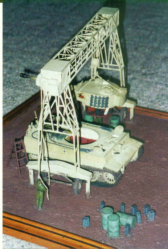
8.1.4 Jig Boom Sockets
Starting in June 1944, three sockets for the Jig Boom, used for mounting
the Behelfskran to lift the rear decking, were mounted on Tigers. These
can be made from 1.5mm wide hollow tube cut to 1mm high. One should be
on the starboard side of the turret 8mm from the side of the turret roof
and 27 from the front, in front of the loader's hatch. Another on the
port side 8mm from the side of the turret roof and 27 from the front,
in front of the commander's copula. The last in the rear of the turret.
This socket was centered and along the rear edge of the roof.
8.2 Spare Track Links
The parts supplied in the kit, L32 A18 and L26, are adequate and can
be made better with just a small amount of work.First the guide teeth
on parts L26 should be hollowed out. A small wire handle can be made for
parts A18 by drilling two small holes in the top of the part and gluing
in a small, 3mm long, handle.Lastly, only two track links should be placed
on the starboard side instead of three. The extra one should be placed
on the port side to make five total.
Conclusion
Well, that’s it. It is my hope that this article has helped in the
building of an accurate mid or late Tiger. It has taken quite a bit of
work, but I found that the end result was well worth the hours of effort
put into the kit.Experienced modelers may wish to take this project a
few steps further. Due to space and time constraints, many of the items
not seen when looking through the hatches or turret ring were left out.
Also some of the scratchbuilt parts were simplified, leaving out unseen
detail. I suggest that those who wish to go further consult the references
listed below.Thanks go to Barry Atkins for helping me proofread the article
and to David Byrden for allowing me to use the pictures and diagrams from
his site Tiger1e.com.
List of References Used
Germany's Tiger Tanks
D.W to Tiger I By Thomas L. Jentz & Hilary L. Doyle. Schiffer
Publishing
Panzer Colors III By Bruce Culver. Squadron Signal
Tiger I Heavy Tank 1942-1945 By Tom Jentz, Hillary Doyle,
and Peter Sarson. Osprey Publishing
Tiger I on the Eastern Front By Jean Restayn. Histoire &
CollectionsThe German Tiger Tanks By Francois Verlinden.
Verlinden Publications
Other books you might want to get that I can’t afford
Tigers in Combat 1 By Wolfgang Schneider & Jean
Restayn. J.J. Fedorowicz PublishingTigers in Combat 2 By
Wolfgang Schneider & Jean Restayn. J.J. Fedorowicz Publishing
Tiger I - 50th Anniversary Commemorative Collectors Edition
By Bruce Culver & Uwe Feist. Ryton Publications
Tiger I and Sturmtiger in Detail By Bruce Culver &
Uwe Feist. Ryton Publications
Tiger & King Tiger Tanks and their Variants By
Walter J. Spielberger. Haynes Publishing
Tiger! The Tiger Tank: A British View By David Fletcher.
HMSO Books
List of Kits Used
Academy #1387 Mid Tiger I
Tamiya #35146 Late Tiger I (for wheels)
Anvil Miniatures AM-35T02 Tiger I late track and lower hull detail set
Cavalier CA-101 Tiger I late ZimmeritTank Workshop 1034 Tiger I engine
Eduard German Floor Plate #2
What seemed like enough styrene plastic to build a 1:1 model of a Tiger
I
|


