|
|
| Home > Articles> Modern > Building a Warrior Mechanised Combat Repair Vehicle |
Building a Warrior Mechanised Combat Repair Vehicleby Graeme Davidson (missing-lynx.com - Best of Show 2002) History The Warrior Armoured Fighting Vehicle can trace its beginnings back to 1967 when the British government first considered a replacement for the FV432 Armoured Personnel Carrier. Over the following ten years, a number of feasibility studies were conducted and by 1977 the parameters of the FV432 replacement were fully defined. The project, known as Mechanized Combat Vehicle (MCV) -80, was awarded to GKN Sankey (now merged with Alvis Vehicles). During the development of the MCV-80, the US XM-2 Bradley was also studied as a potential replacement. In June 1980, the British parliament gave the green light to the MCV-80. Work on the prototypes had been ongoing, and so for 1980, three vehicles were ready for trials and evaluations. By November 1984, the Warrior, as it was now known, was accepted for service in the British Army. Full production began in 1986, as did contracts with the company to produce specialty variants of the Warrior. By spring of 1987, the first production Warrior was in use by the British Army, and the first Warrior equipped infantry Battalion was operational in the BAOR by mid-1988. Due to forces reduction in the British Army during the second and third production cycles, the amount of Warriors required by the Army was reduced. In all, some 789 Warriors entered service, with the majority (387) being the typical Section Vehicle. Other quantities were:
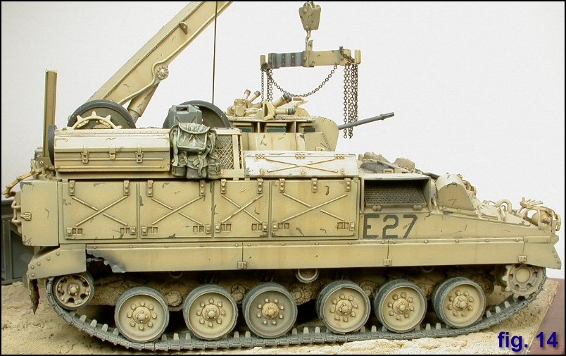
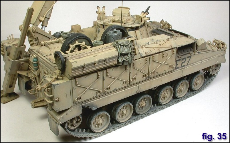
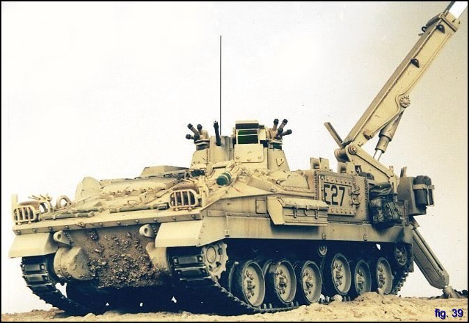
During Operation Granby (Desert Storm) all variants of the Warrior were deployed, including the Observation Post and Battery Command Vehicles which were just entering service. Prior to the ground invasion, many Warriors were fitted with a side and glacis plate appliqué armour, which can also be seen on certain Warriors used in Bosnia, Kosovo, and other theatres where there is a high threat level. Though the applique armour was not fitted to the MCRV, it did receive GPS navigation systems and maintenance free batteries. General Characteristics The Warrior hull is made of all welded aluminum giving a much higher degree of protection than the FV-432. The driver sits at the front left and his single periscope can be augmented with an image intensifier for hatches down driving at night. Warriors are being retro fitted with a 3 periscope hatch to give the driver better side visibility when under armour. The engine produces 550 hp and is mated to an automatic transmission with 4 forward and 2 reverse gears giving a max forward speed of 75 kph and a range of 660 km. Torsion bar suspension supports six roadwheels with a front drive sprocket and rear idler wheel. Three return rollers support the track. Shock absorbers are on the 1st 2nd and 6th road wheels. The vehicle uses a Halon fire extinguisher system; the two extinguishers are mounted in the front of the vehicle and vent into the engine compartment. 5 hand-held fire extinguisher are also mounted on the vehicle, 3 outside and 2 inside. The prototypes of this British designed special variant were made in 1986, and were also later deployed operationally to the Gulf War. The MCRV has a crew of five consisting of the commander, driver, gunner and two vehicle technicians, though I suspect all crew members are of a REME trades background. Mounted on the left rear of the hull is a hydraulically operated crane which can lift a maximum of 6,500 kg, giving it the capability to hoist a complete Challenger 1 or 2 powerpack. A hydraulically operated stabiliser leg is lowered to the ground before the crane is used. An air compressor is provided for the use of Snap-On tools and to assist work in the field and an electro-hydraulic pump allows the vehicle to change its own power pack. The manually operated one-person turret is armed with a 7.62 mm L94A1 Chain Gun with 2000 rounds, and eight 66mm smoke grenade dischargers. The MCRV can tow the Alvis T4 high-mobility trailer, which weighs 10,500 kg fully loaded and can carry a complete Challenger or two Warrior power packs. The Mechanized Repair Vehicle Recovery (MRV-R) is virtually identical, except it has the addition of a rear mounted hydraulically operated winch with a capacity of up to 38,000 kg. To hold the MRV-R in place during recovery tasks, a large earth anchor can be lowered into the ground.
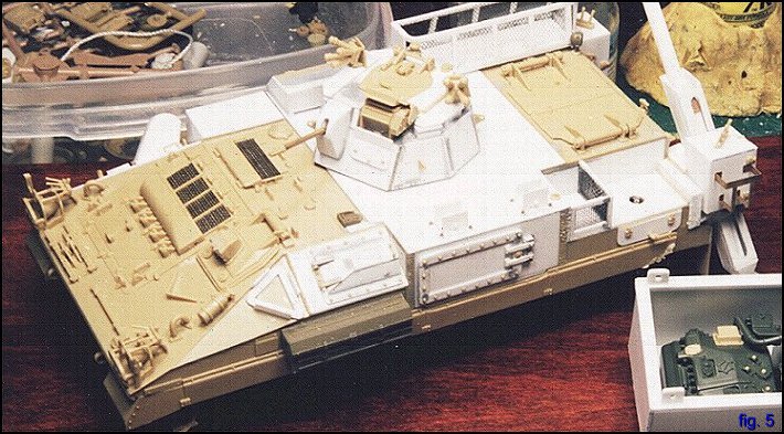
Building the Warrior The Academy warrior kit was released in 1996 and provides parts to build the Section vehicle in two variants; with or without the bolt-on armour that made its debut during Op Granby. The kit comes with markings for 3 vehicles; a tan coloured "Desert Rats" for the Gulf, a green and black camouflaged British Army of the Rhine, and the all white UNPROFOR from Bosnia-Herzegovina. Other theatres (SFOR, KFOR) could easily be depicted with Archers modern series of dry transfers.
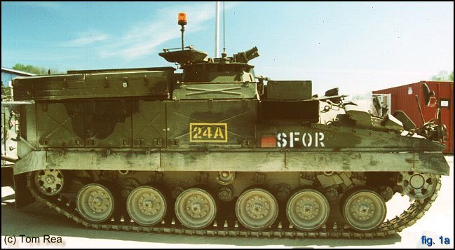
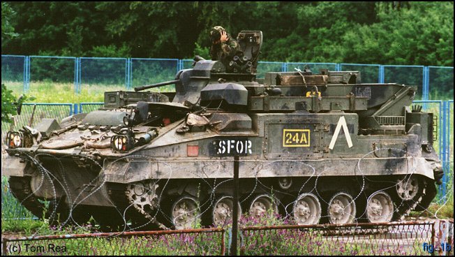
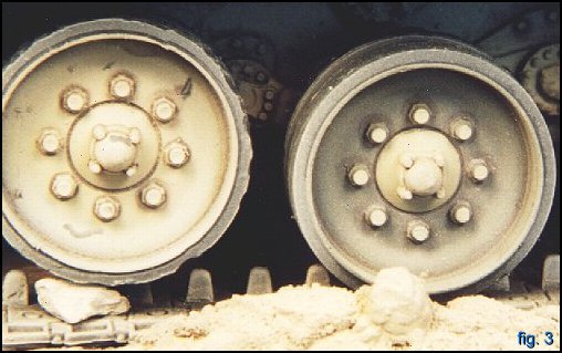
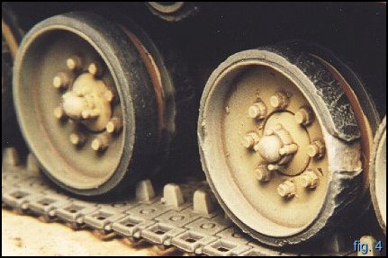
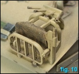
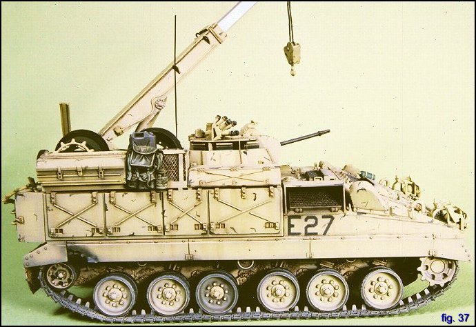
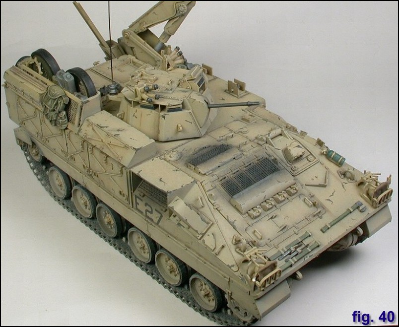
I decided to build the MRV-R variant as most of the base kit could be used, and the majority of the parts that had to be scratch-built could be made with sheet styrene. I began in the usual fashion of gathering references, which proved to be difficult as most books on the Warrior focus mainly on the Section vehicle, as do most of the photo records from the Gulf War. Special thanks to John Tapsell who provided photos of a BAOR vehicle, and whos own MRV conversion can be found at www.armouredengineer.force9.co.uk. Accurate Armour offer a complete multimedia kit of the MRV-R (among other specially engineered variants) for those who would rather ride the resin road. I also used Janes Armour and Artillery 2001 and the Osprey New Vanguard, though neither of these provided much info in the way of repair and recovery variants. I followed the kit directions beginning with the lower hull and running gear. The tracks on this kit can sometimes be a bit tight, so I positioned the torsion bar arms in the compressed position. There is a slot for the arms to slide into the hull, but there is enough free play so that the track will not be too tight. I wasnt overly concerned about getting all the wheels level as I wanted a bit of articulation in the suspension. However, on the drivers side #4 wheel, the arm dried in a more compressed position than I intended. Rather than risk breaking it off to adjust it, I placed a rock between the roadwheel and the track pad. Why do this? In the field, AFV crews use this method to raise roadwheels up off the track surfaces so that they may be replaced. Just like you wouldnt try pulling off a car tire before you jacked the chassis up. Except, my rock should be on the inner roadwheel. Hows that for an excuse for not having your roadwheels sit level? Once the suspension had been fitted, I assembled the wheel pairs. To impart a well-used look, I attacked the rubber portions with a dremel tool. I varied the wear and tear on the wheel quite a bit; some have the rubber shorn off exposing the metallic colour of the rim, while others are quite new, still wearing their BAOR green finish. Note that the hubs and bolts are not part of the issued road wheel, which is why they are still in the tan paint. If you really want a dose of AMS, the nuts that go over the studs are a zinc colour, as new nuts are always used to attach a new wheel. Shaky hands here draws the line at that though! Most photos of Gulf war AFVs do not show the level of wear I have depicted. One of the ancillary benefits of a 96-hour war is less track maintenance. Next came the main surgery to the upper hull. I began by chopping out an L-shaped rectangular segment that would form the base for the crane. This was filled with .040 styrene, as I wanted a sturdy base for the hull. Not much else has to be cut away from the kit as most of the modifications are added after stock assembly. Moving clockwise around the sides of the hull from the crane base, I added a hinged panel behind which would be located the various levers to actuate the crane and winch. I glued this shut. Next was a small storage cage built with strip and the nylon mesh that came with the kit for the turret basket. This nylon mesh has a nice fine weave, but you need a new blade to cut it or it will fray very easily. Continuing up the side of the hull is the NBCD door access. On the section vehicle this is hinged to the front. For some reason, on the repair variants, it is hinged to the rear. I blanked off the area with some thick styrene and made my own door out of strips. Using a chisel blade, I carefully shaved off the bolt head and some hinge detail from the stock nuke door. These were then glued around the doorframe.
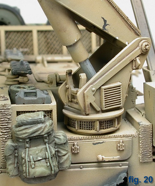
In front of the access door is another hinged lid, which was a bit trickier as there were a few compound angles that had to be filled. I binned two or three of these before getting the shape and fit right. This time the bolt detail was chiseled from the armour plates that came with the kit. One of these days, I will buy a P&D set instead of sacrificing Warrior armour and Challenger road wheels for bolts! Just below the access door is a storage box robbed from the AFV Club scorpion kit. The Scorp also donated some stowage in the form of an idler wheel. The MRV-R I was depicting would have been supporting a Battlegroup equipped with Scorpions and Challengers, so I wanted to tie some of the stowage into that theme. I added a triangular bracket in front of the access hatch that holds the hook & pulley assembly when the crane is in the travel position. The rest of the kit details on the glacis plate were added according to directions, but I left them off until near the end of construction. The kit would get a good bit of handling during the scratchbuilding process, and I didnt want to break off any of the delicate cam pole receivers or headlight guards. Funnily, the cam pole receiver tubes are molded in two different diameters; some of them I was able to hollow out with my smallest drill bit, others split open when I tried this effect.
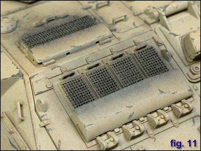
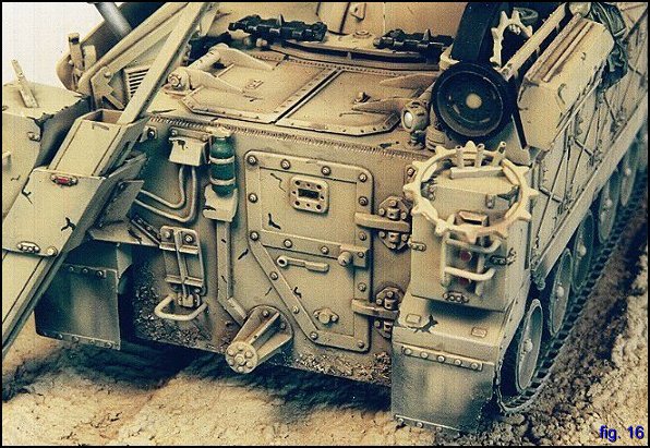
I also undercut the fire extinguisher retaining straps and added some more of the kits mesh for engine screening. I was quite pleased how this turned out, as the nylon mesh is actually woven - an effect that is difficult to duplicate with a PE part. Working my way down the right side of the hull, I added the curved vent cover, an upside-down J shaped thingy (anybody know what this is?). The rear opening to this vent was covered with mesh as well, but youd have to be 1/35 scale to see it. The next big vent was covered with a more open weaved mesh called Thule. You can get this stuff at fabric stores in the wedding dress material section; I think it may also be known as funeral veil (how apropos). For a few dollars you get a life time supply of mesh. Its a little big for most 35th applications, but it does have its uses. Dont even try and explain to the sales clerk what you want it for Anyways, this vent was covered with a styrene box, presumably it is some short of heat shield on the real vehicle. Often, they are seen with large creases, dents and muddy squaddie boot prints on the "roof" from soldiers walking across it. Behind this vent, I built the series of four stowage boxes of three varying sizes. The roof of these boxes was just extended from the hull top to a line parallel to the side edge. The access doors to the storage bins were cut from .020 styrene. Before gluing them to the hull, I had to cut out eight latches at the bottom corners of each door. This was a little fiddly getting all 8 cuts square and of a similar size (someone should make a knife that cuts a 90 deg notch like a mortise maker thingy on New Yankee Workshop, only much smaller). This was not the time to rush a step. Once each hole was cut, I added a short bit of stretched sprue to replicate a sliding handle. Upper hinges were fashioned from styrene strips and detailed with bolts from a Challenger roadwheel. Now, Im not advocating that you sacrifice a Challenger kit for simply for its roadwheel bolts, but a friend had tossed his in the garbage, so I decided to pilfer it (not that I make a regular habit of going through peoples garbage, though I was amazed at the amount of cheap red wine bottles in Nats dumpster!). In addition, the bolt-less Chally wheels were drilled out and later used as on board stowage. Waste-not, want-not! Each of the door lids have an embossed X pattern, with one line of the X bisecting the other. I used stretched sprue again, lightly sanded flat on one side to give this effect. Looking at the real MCV now, I think my ridges are too narrow. Above the storage bin is a long rectangular toolbox with a sloped lid (I think this also came from the Scorpion), which was widened with more styrene. The X pattern on this box is too squashed, and it doesnt have the gap between the two ridges. The other toolbox I added on the driver side below the hook bracket has the most accurate looking embossed ridges.
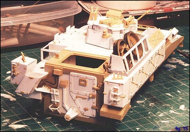
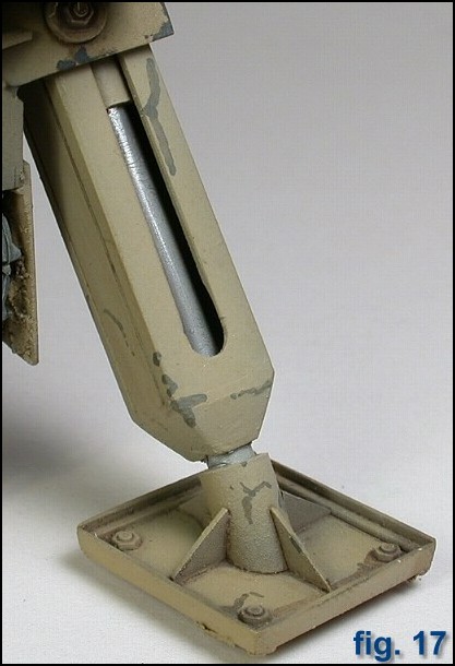
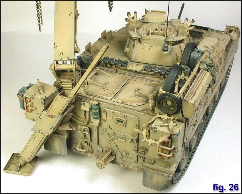
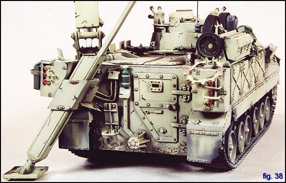
The rear of the vehicle involved the most scratchbuilding so far; each of the storage bins mounted on the top left and right of the rear hull had to be cobbled together. The left hand bin has some odd angles as it must fit to the stabilizing leg bracket, itself at a compound angle to the hull. The stabilizing leg actually points at a slight out and away angle, more on that later. The Warrior kit does come with bins for this area, and I was able to shave off small details such as latches, hinges, and marker lights and make use of them on the scratch bins. If you dont have an x-acto chisel blade in your arsenal, go and try one out! I made brake and signal light guards from heat formed styrene rod. The double door of the Infantry section Warrior was filled in with a sheet of .040 trimmed to fit the opening. The MRV series use a single door hinged on one side. Im told the door actually opens in separate top and bottom halves, just like how the quartermasters door functions! Again, numerous details from the kit doors were salvaged and used to dress the single door. The rear has a hook up for that huge Alvis trailer (hmmm ). The discs were cut out using a circle template and the six strengthening ribs are .010 styrene cut into triangular shapes and slotted in. Various attachment points for power and hydraulic lines were added, as was a folding table / anvil. The leg used to stabilize the MRV when the crane is operating was next. As previously mentioned, it sits at an odd angle to the vehicle, pointing out and off the vertical to the rear hull. I made the basic shape of the leg from hollow rectangular tubing. The front and back had parallel groves scribed into them with an Olfa-cutter, while the sides of the leg had segments cut out. Inside the leg I made a hydraulic ram out of interlocking cylinders. Coming out the top of the arm is a channel that the leg sides up and down on. Some pictures have this channel sticking up, others, you cant see it at all. Id have to see the leg in action to properly describe how the whole thing functions. The base of the leg was finished in a trapezoidal shape made with miliput. This was allowed to harden overnight and then I began work on the baseplate, which is basically a square plate with some channel styrene mitered around its edge. The socket for the baseplate was fitted with a slightly larger diameter tube to attach to the ram. I think on the real MRV, this is actually a ball and socket joint, but I wasnt planning on moving it around too much anyways.
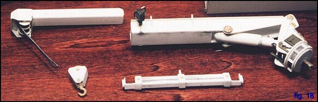
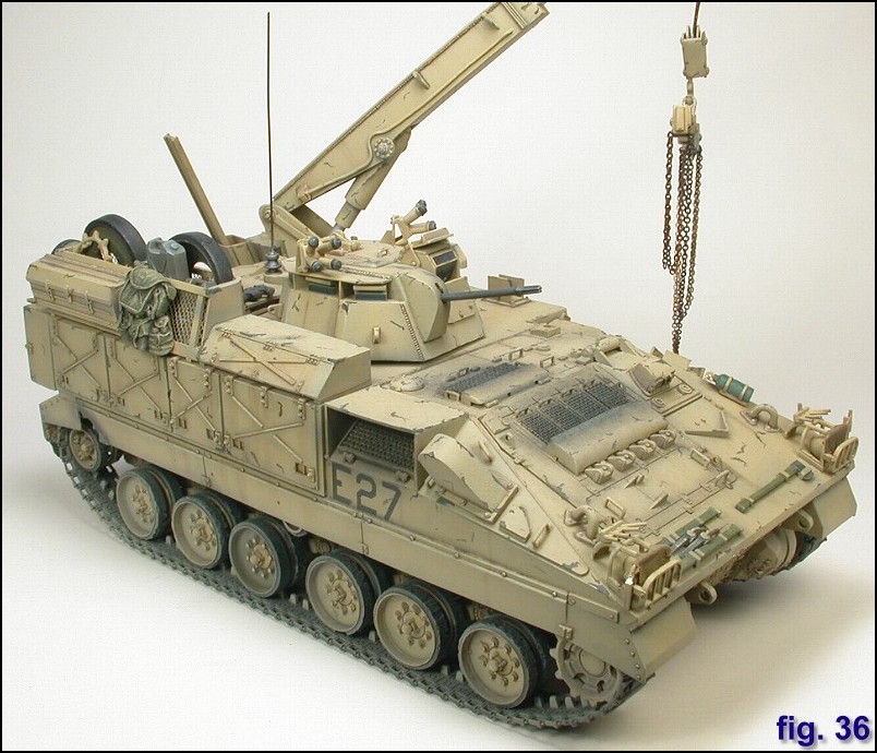
It was around this time that my project changed from and MRV-R to an MCRV. I love the look of that earth anchor used to hold the MRV-R in place when winching, moreover, in the upright position, the curved blade portion would be a great place to store all kinds of personal crew gear. However, building that piece confounded me. I did not have any good reference photos at the time (of course when the model was all finished, Tom Rea provided me with detailed photographs taken from every conceivable angle!), and I just could not get all the angles right. After a weeks worth of shooting at the walls of heartache, I decided to drop the anchor and make the more common MCRV variant. I then began to work on the crane. The key to this was finding the right size of rectangular tubing, unfortunately the only tubing I could find had a square cross section. I was able to locate a rectangular piece for the extension, but the main body of the crane was built from scratch. I decided that the crane should be semi-poseable, so the extension can slide in and out of the crane housing and can traverse 360 degrees. I based how elevation mechanism would work on the launcher from an old Nike-Hercules missile kit; building an elevating ram out of 3 different diameters of rod & tube I was able to raise and lower the crane. The rounded top of the main cylinder was made with miliput.
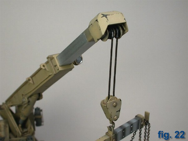
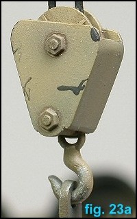
The base of the crane was prepared with discs using an Olfa circle cutter and some T-beam styrene. The crane also has some kind of vents around its base with I simulated with small pieces of mesh. I modified a Tamiya Landrover searchlight and attached it to the left side of the crane. I wish I had used a MV lens in that as it is quite prominent on the finished model. For strength and mobility, I built the base around a brass tube that fit into a hole drilled in the hull. The extension arm was topped off with a pulley set and housing. The pulley set wasnt too difficult, except that circle size is too small for a compass cutter, and too large for a P & D set and had to be cut out and sanded to a circular shape the old fashioned way. The housing for the pulleys is about the size of your thumbnail and is made up of 13 parts. This was a good nights work alone. Even taking my time, I still find that I sanded the edges too much the real cover has very distinct edges whereas mine have been rounded off.
Since I planned to have a something hanging from the crane, I stayed away from thread, as it allows the load to sway unrealistically. In this case I used lead wire, the downside of which is keeping the lines straight (especially after 2 flights on Air Canada) thus giving the impression that it is bearing a load. The hook assembly was made with small discs sandwiched between some triangular shaped bits, I used the spare hook that comes in the Academy M-113 Fitter kit.
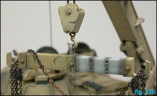
A lifting bar was made with two lengths of square rod glued together and drilled out. This adjustable bar is used to distribute the load when moving items such as spare engines and pallets. Details on the hull roof were relatively straightforward. I put together a bracket to hold the lifting bar for travelling and an open stowage rack made from strip styrene and Thule mesh. The cargo hatches were used from the kit; in fact, the aft portion of the Warrior was left fairly untouched. However, the cargo doors on the MRV hull look to be a slightly different shape from the Section vehicle. Naturally, this was realized after I glued on the kit ones. To draw attention away from this, I attached part of a Challenger towing assembly and two Challenger track links just forward of the doors.
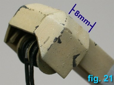
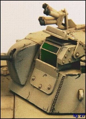
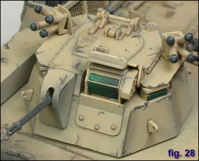
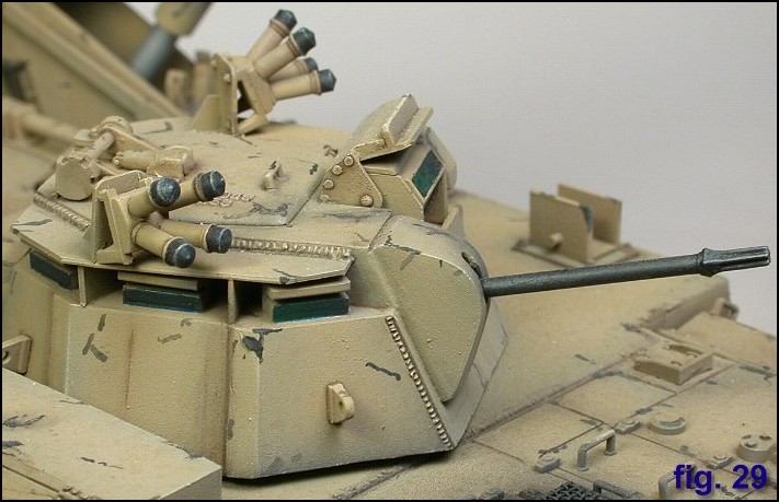
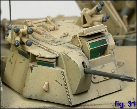
I was now ready to tackle the crew commanders turret. I filled in the hull where the 30mm Rarden turret would go and laminated over that patch with thin sheet. I cut the base of the 8 sided turret out of .040 styrene, slightly smaller than what I intended the final size to be. I built up the inside of the turret to the correct height with sections of wide tubing and Lego. I then cut the roof of the turret that the vision blocks rest on. This was a trial and error process (process= several hours of uninterrupted profanity followed by dizziness and nausea from methyl-ethyl-ketone fumes) until I got a shape that more or less formed the correct angles for the side plates (3-view plans? 3-view plans?! We dont need no stinkin 3-view plans!). The side plates were cut oversize and trimmed to fit. A second layer of plating was added to lend to the overlapping effect of the turret armour. Fortunately, I was able to use the kit supplied vision block, hatch, AMU, and smoke grenades. For the latter, simple brackets were made with .020 sheet, though I see now that I neglected to add the conduits for the electronic firing system. Hey, by this time I was also seeing cellophane flowers of yellow and green! The periscopes were made from square rod nestled inside L brackets, and were positioned at appropriate angles around the turret. Above the vision blocks sits a second roof on which the hatch and smoke grenades were attached. I then made the mantlet for the L94 chain gun. This one morsel took as long as the entire turret! I made it by laminating thick sheets of styrene into a solid block. Then I slowly sanded away to get the tapered shape. I continually checked the profile from all angles as I went and was able to get the rough shape. Rather than fill in the sanding marks, I superglued thin sheet to the front and oversized sheet to the sides and then trimmed to fit. A pilot hole for the gun port was drilled through the block using the largest bit in my set. I used the drill to shape the max and min elevation slot and cut a short piece of brass tubing for the gun barrel. The kit flash-suppressor was superglued onto the end of the tube.
The turret just needed some weld bead detail that I made with thinly stretched sprue brushed with liquid glue. This was allowed to set and was textured with a soldering iron set on low. A fine tip was used to melt the weld beads into the sprue. This was given a final wash of liquid cement to remove any hairs and to soften the texture. While the soldering iron was hot, I added weld marks to the hull, sides of the crane, and cutting torch grooves alongside the NBCD hatch and rear hull. I must admit Im really satisfied how those weld beads turned out, they are my favourite feature of the whole model I had my weld-bead mojo working that day baby. For whatever reason though, Ive been unable to get that same effect since!
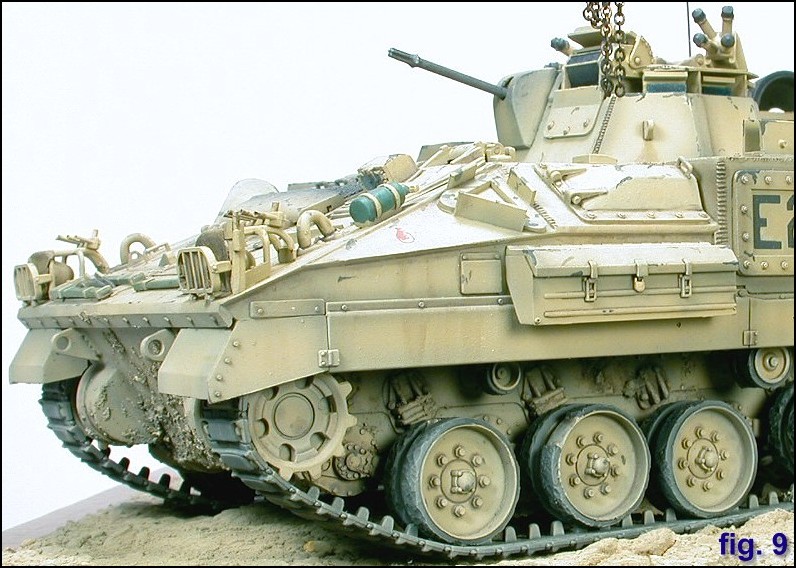
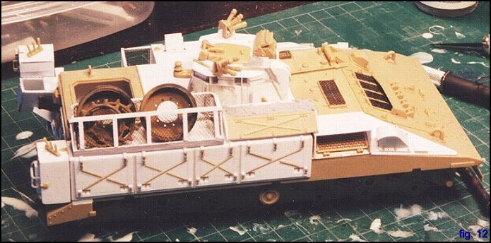
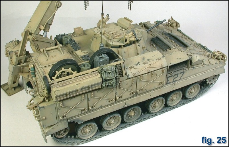
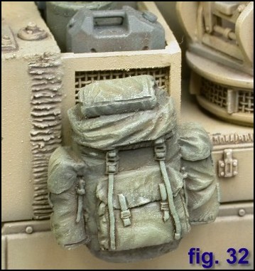
All of the major subassemblies were complete and I began to fiddle about with placing stowage. I addition to the salvaged Challenger roadwheels, I discovered that the aggressive use of a sanding block could be used to make the drive sprocket ring. I was as excited as a little girl! I used a couple of backpacks from AA and VLS (I know its Vietnam vintage, but soldiers often deploy with non-issue personal kit especially REME types), plus AAs Jerrycans and oilcans. Some spare tracklinks rounded it all off. One thing about an AFV with all those side bins is that it probably would not have a lot of external stowage.
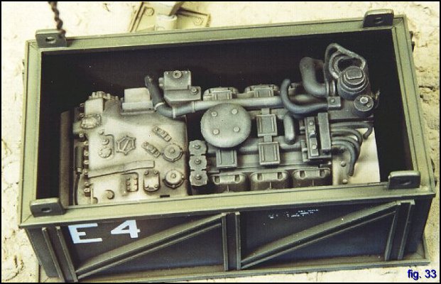
I used the engine from the Tamiya Marder and detailed it up a bit with some lead wire. Since this part comes with hardly any sidewall detail, I went the easy route and dropped it into a close fitting shipping container. Yeah, I know the Warrior uses a different engine, but I took a little license. Plus, the MMM show was less than a week away and I had to get painting! Before painting, I added a few days worth of mud to the hull. This was made with tamiya putty, testors liquid cement, and marble dust. I glopped it onto the front hull in a manner I saw on a Desert Storm Scorpion.
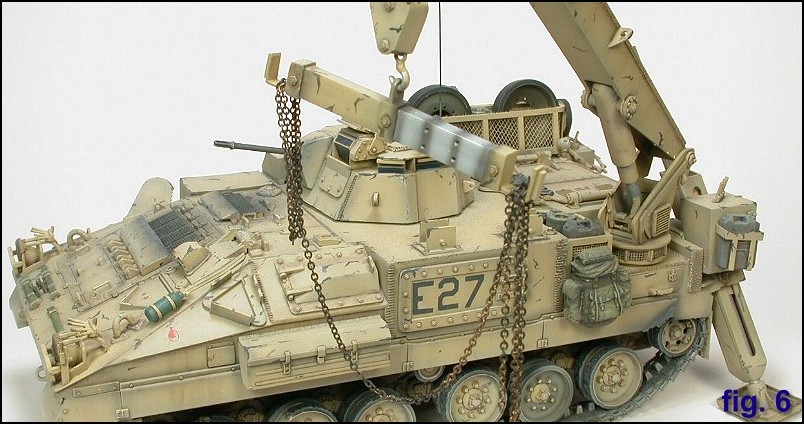
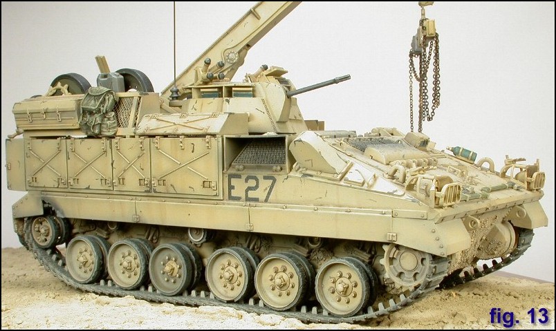
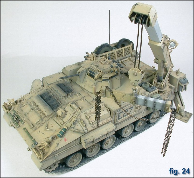
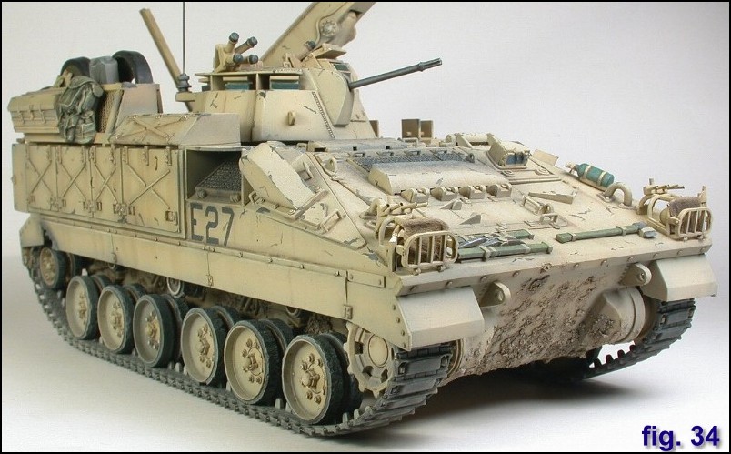
I left the kit in its sub-assemblies for the painting process. Using Tamiya acrylics and a Badger 200 airbrush throughout, I gave the model a dark brown primer / pre-shading coat followed by a mix of Buff and Desert Yellow. This was diluted roughly 50:50 with Tamiya thinner and sprayed on in 3 successive coats, allowing the darker brown undercoat to just show through. I sprayed a very thin mix of flat black over the engine grills and machine gun. This was left to dry overnight before I applied a localized wash of Burt Sienna (or was it Raw Umber? I always get the two mixed up) oil paint, concentrating on the bolt heads and panel lines. While this was drying, I sprayed the stowage. The kit bags were given a coat of flat black and then two coats of olive drab; the last one mixed with desert yellow to lighten the olive. The bags were also given a brown oil paint wash and set aside to dry. I then picked out the details such as pioneer tools, fire extinguishers, and signal lamps. Vision blocks were painted gloss black and coated with a blue Staedler maker that gives a kind of oily translucent sheen to the "glass". Once the wash had dried, I decided that it had enough depth without having to dry brush. I wanted to show the BAOR black and green paint beneath the hastily applied desert tan (I think the official colour is Stone), so I made a few paint chips. Then I made a few more, and so on, and so on, until I turned into a brush-stabbin, paint-chippin psychotic hopped up on goofballs. For me this turned out to be the most disappointing aspect of the finished model. This is a technique I find quite difficult to pull off, as my "chips" always seem to look like brushed on paint. Next time Ill try the masking technique described by Rhodes Williams in AFV Modeller Issue #3. To tone down the chips, I sprayed a heavily thinned coat of buff. The kit was mounted on a frugal desert base with the crane and lifting bar positioned above the engine. Its one of those displays that cries out for a few figures. Nevertheless, as my figure painting efforts resemble Marilyn Manson meets Night of the Living Dead, I decided to forgo that addition. Maybe there was an incoming Scud alert and they all ran inside the track? Or perhaps Ill just tell you that its tea-time and theyve all gone for a brew yeah, thats it! Out came the buff mixed with a little sky grey this time, and the lower running gear was integrated into the desert colour with a coat misted on from about a foot away.
The model was photographed under various lighting and background colour conditions. I also experimented with different speeds and brands of film, hence the variety of shades of desert tan. The most accurate colours were achieved by using Fuji 100 ASA film against a bluish-grey backdrop and three 750w photoflood bulbs. This was my third attempt at scratchbuilding, and despite a bit of a learning curve compared to previous efforts, it continues to be a highly satisfying aspect of the hobby. Next up a Roland SAM on a MAN 8x8!
|
| |
|
Home |