|
|
| Home > Articles > Modern > Modelling the M-60A1 |
|
I have built up Tamiya's M-60A3, kit # 140 (includes the parts for M-60A1 which they refer to as the 'Marines version'); Academy's M-60A1 Israeli 'Blazer', kit #1358; and Esci's M-60A1 Israeli 'Blazer', kit #5042. Tamiya also have a U.S. Marine M-60A1 with reactive armor (#157). Academy have this version as well, calling it USMC M-60A1 RISE/PASSIVE (#1349) and also released with an M-9 Dozer Blade. Academy also made the Israeli 'Blazer' tank with a mine-roller set. Esci made an M-60A1 and M-60A3 TTS, and apparently the Esci kits will be re-issued under the Italeri label (yay!). I wont even consider Trumpeter's kits, as they are poor copies of the Tamiya kits.
Kit Build-ups:
All model kits were assembled following their suggested instruction sequences for the most part, only using an X-acto knife and files for cleanup. Testor's liquid cement and white glue were used for assembly (white glue so I could disassemble some parts later as I intend to detail these kits further). Each one was built as a basic 'vanilla' M-60A1, with none of the extras for special versions. I worked in stages: lower hulls of all three kits first, then upper hulls followed by turrets. This way I could keep the differences fresh in my mind. I will use point form to describe my observations during assembly, the pros and cons. For the time being, they are also left unpainted.
Lower Hulls: Tamiya Kit.-Well start with the old timer first. The hull sprues are dated 1970 (Im only 5 yrs older than they are!) while the (new M-60A1/A3) turret was made in 1988.
-Only kit that has a drivers position and seat (although any resemblance to the real thing is purely coincidental!)
-The lower hull looks like Swiss cheese; there are so many motorization holes in it! The entire lower hull is a multi-piece affair: you have to attach two strips on each upper side; these pieces have the return roller mounts and shock absorber mounts on them. If you are lucky you will only have to file the mating pieces flat for a good fit. If these pieces are warped at all, youll have a bitch of a time getting them together. There is no cast texture on any of the lower hull parts.
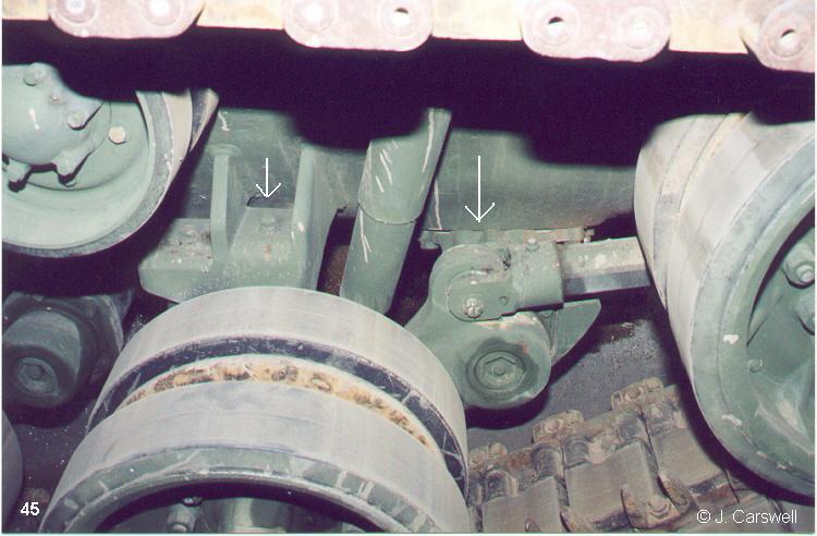
-Parts B5 and 7, which are mounts/dampers for the idler wheel, have the ends of the shocks (dampers) inserting into a hole in the hull, just above the first set of suspension arm mounts. THIS IS A BIG BOO-BOO. The shock should attach directly to the front suspension arm itself, not the hull (see photo #45 below). All three kits have this same design for some reason. (MR Models have recently come out with an M-60 suspension update set, which fixes this problem)
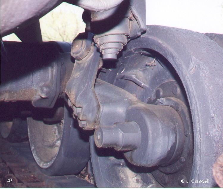
-Shocks (B29) dont meet up with the suspension arms at all, they just stick out wherever. I would suggest attaching the suspension arms first, clip off the pin on the back of the shock, then cement using the top attachment point and the point where the bottom of the shock meets the suspension arm. Of course, the road wheels hide this area so if youre not too picky, you could leave it up to you! (See photo #47 below).
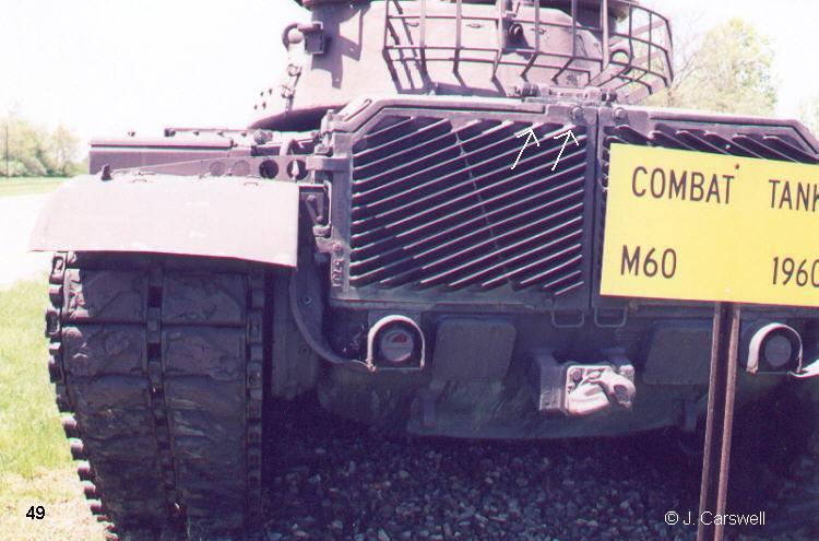
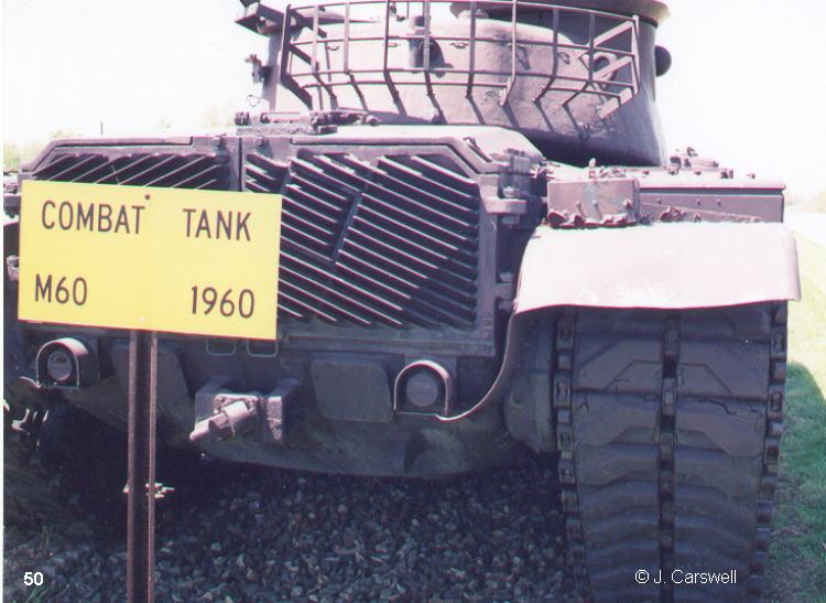
-The rear panel/engine grills (C15) has a few problems. The towing pintle is poorly detailed, the taillight lenses are featureless and the taillight guards are molded as solid pieces. There is quite a gap at the bottom when this piece is attached to the hull proper. When complete, the upper hull slides over the rear panel, but there should be a raised piece, which interlocks into the upper hull (see photos 49 and 50 below to see what Im trying to describe). Also, the large hinges on either side of the grills are molded on the panel and are only ½ there. There should be curved dust/mud skirt extensions between the rear fenders and curving down to the tail light guards, these are missing.
-Tow hooks on B23 (front) and C1 (rear) seem to be shaped funny.
-Running gear: drive sprockets and idler wheels press on to metal axle shafts this is good as the tracks end up being fairly tight. The road wheels and idlers are attached to their axles by pressing poly hubs into the road wheel and on to the axles. The poly hubs fit poorly and paint doesnt stick to them very well. There are no mud clearing holes in the drive sprocket hubs (common problem to all 3 kits). The tracks supplied are the rubber band style and look OK, but if you look closer you see that the guide teeth are in the centers of the track links, instead the teeth should be part of the connector between the links.
-When you connect the upper and lower hull pieces, there are annoying gaps at the rear sides, which are quite tricky to fill.
-Apparently this kit sits too high on its suspension, if only by a few millimeters. It would be fairly easy to correct this by clipping off the end of the pins of the suspension arms so you can adjust the height as you wish, or you could do this if you wanted to show animated suspension on a diorama.
-The Tamiya USMC M-60A1 version comes with M-48 steel road wheels rather than the ribbed aluminum ones seen on the M-60's (from their Sgt. York kit!). Apparently the steel ones were tougher, and you can see different combinations of steel/aluminum road wheels on some tanks.
 |
 |
 |
 |
 |
 |
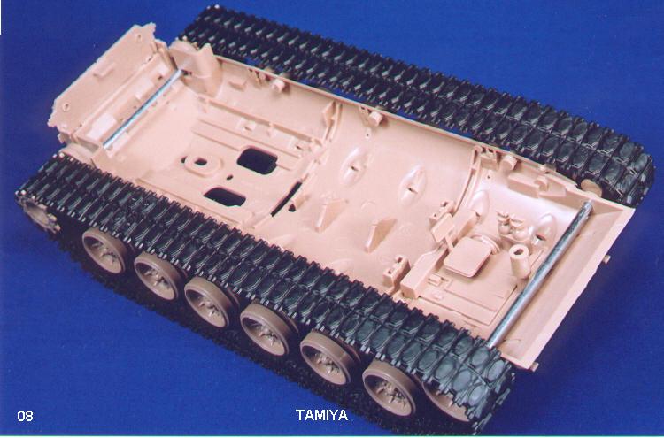 |
Photo captions:
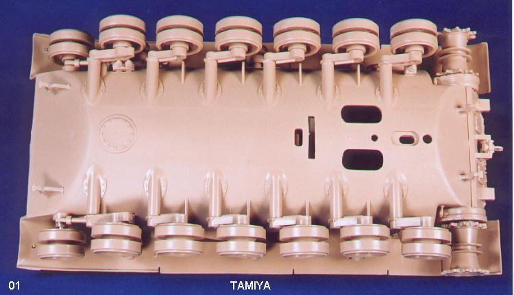
(01): 'Down Under' view showing (in) famous Tamiya motorization holes, also poor joint of rear panel and molded-on tail light guards.
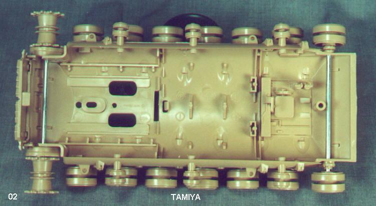
(02): inside the lower hull. Metal shafts great for supporting idlers and drive sprockets. Also can see driver's position.
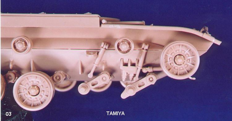
(03): a whole pile 'o nastiness showing the 'unattached shocks', gaps around the poly caps for the road wheel hubs, and poor fitting upper and lower side hull pieces. Also note how the damper for the idler wheel is connected to the hull. Compare this with photo 45 of the real thing below.
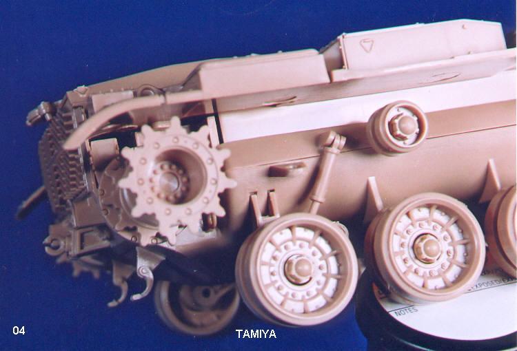
(04): more 'gappage' behind drive sprockets. Lots of extra work to fill in.
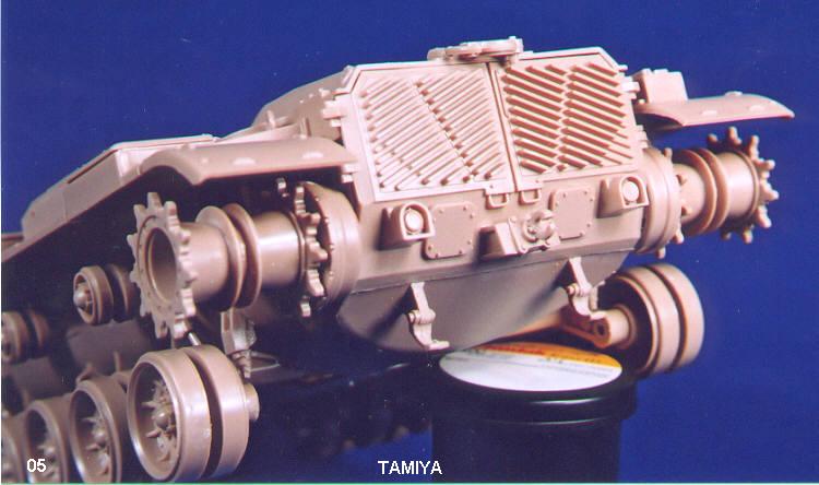
(05): rear end, again we see the molded on tail lights (with no detail), missing curved dust skirts.
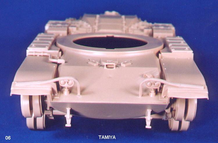
(06): front lower hull, couple of sink marks center of upper and lower plates.
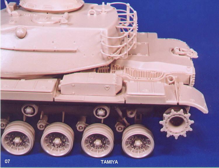
(07): rear hull side, gap between rear panel and upper hull piece, '1/2' hinges on the side of the engine grills.
(08): another view of the inner lower hull, tracks on.
Academy Kit:
-Sprues marked 1990, but are essentially a reworked copy of Tamiyas kit. To that end, you get the same multi-piece lower hull and suspension problems. There are more knockout pin marks and sprue attachment points to clean up as well. Also includes poly hubs to hold road wheels on.
-Not as many motorization holes in lower hull (only one this time!)
-No metal shafts for the axles. Plastic axle inserts used. Much weaker, good thing the track is a loose fit.
-Two types of tow lugs provided, possibly for US/Israeli differences.
-Shocks fit worse than Tamiya ones.
-Suspension arms fit very tightly into their attachment points. Have to be careful you dont break them.
-The rear panel has better detail. The taillights are detailed and are separate pieces. The panel fits a little better and the grill hinges are separate. Dust/mud skirts are provided this time.
-Tracks If you have the Israeli Blazer version, you are provided with Merkava type tracks and drive sprockets. Strictly speaking, these were not used on basic Israeli M-60A1s, just upgraded M-60s and upgraded M-60A1/A3s known as Magach 6B GAL. I would use AFV Clubs excellent T-142 track links with the proper drive sprockets (both types of sprockets are provided in the kit). If you have one of Academys USMC kits, you are provided with the rubber band style almost exactly like Tamiyas, only these ones fit a little looser (almost too loose).
-USMC M-60A1 RISE/PASSIVE kit also comes with steel road wheels, with separate vinyl rings for the rubber part.
 |
 |
|
 |
 |
 |
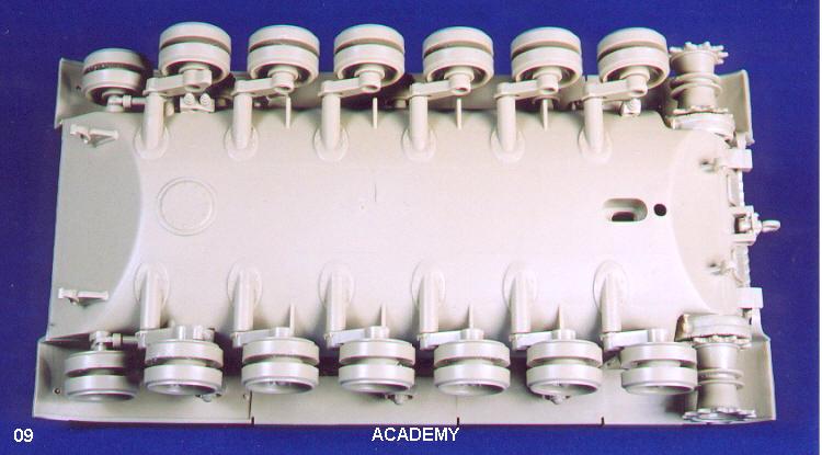
(09): fewer holes to fill! Getting better.
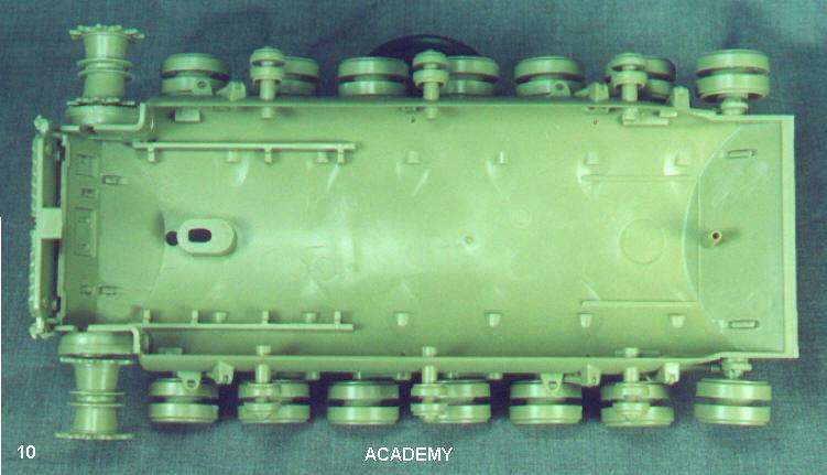
(10): inside of Academys hull - a little cleaner, no spot for a driver here.
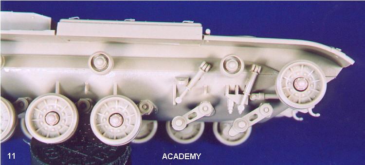
(11): gah! Shocks fit even worse than Tamiyas. Same poly cap setup on the road wheels, but gaps are even worse.
(12): similar gap problem at rear.
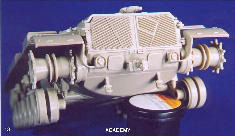
(13): separate, detailed tail lights as well as separate hinges for the grills. Curved dust skirt parts included. Open space behind final drive housing should be filled in.
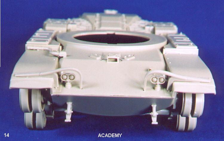
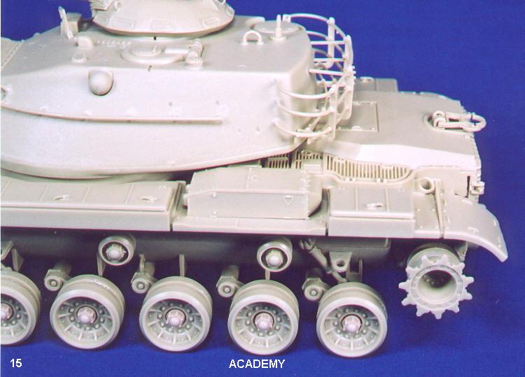
(14): front hull view, no difference from Tamiyas, except no sink marks.
(15): still a gap between rear panel and upper hull.
Esci Kit:
-After putting together the first two, this one was a dream. One-piece lower hull with a nice cast texture.
-Shocks actually attach to the suspension arms.
-Separate tail light assemblies.
-Separate dust/mud skirt pieces.
-Road wheels are two piece (inner and outer) plastic. No goofy poly hub.
-Rear panel is engineered much better, fits nicer and looks better.
-Tracks are link-and-length injection plastic. Difficult to clean up, lots of punch-out pin marks. Problems assembling - had to add an extra link, then the track was too long, but couldnt make it fit without it - was too short then! I ended up having to modify and use two of the extra links given to use as stowage.
 |
 |
|
 |
 |
 |
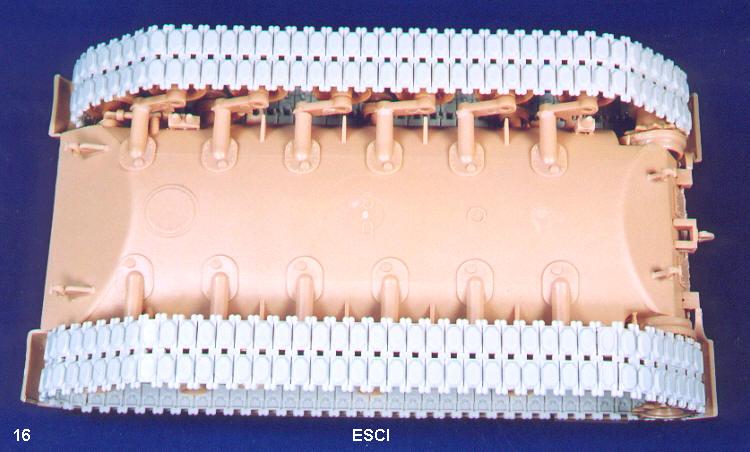
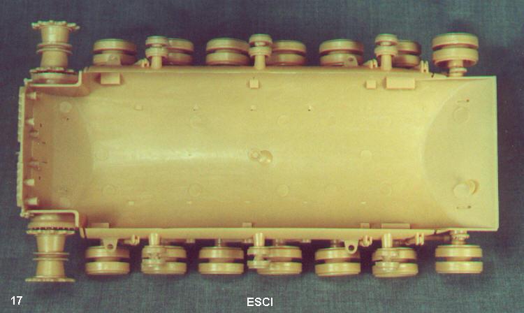
(16): no motorization holes! Had to put the tracks on, as they are plastic length and link type.
(17): clean, baby, clean!
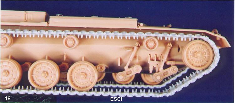
(18): shock problem looked after, but still a weird slot just behind idler wheel. Front idler damper still attaches to hull. Sink mark problem in center of upper suspension arm attachment point. Road wheels are cap less!
(19): another slot in front of the drive sprockets, never could figure out why these were here.
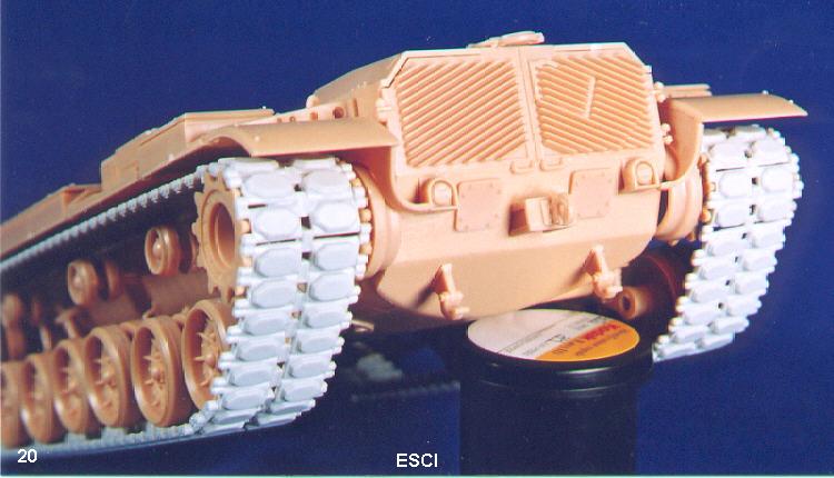
(20): top of rear panel interlocks with upper hull as per the prototype (see photos 49 and 50 below). Also open space behind final drive housings, which needs to be fixed.
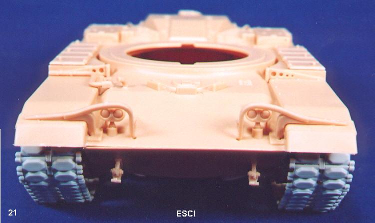
(21): things to note: bilge drainage tube, separate fender support braces with holes, periscopes all up (but drivers hatch molded closed). Barely visible are the drainage slits on either side of the middle periscope and braces behind the headlight guards.
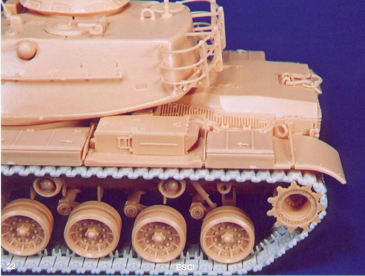
(22): better fit between rear panel and upper hull. Good view of side loading air cleaners.
General Comments for all three kits:
-Regarding the lift rings on the sides of the hull, judging from photos, there should be either the two larger lifting lugs, OR the three smaller lift rings, but not both, as all of the kit instructions would have you do. This was one of the last things I noticed while I was finalizing this article.
-It was recently pointed out on the Internet that the tracks stick out slightly past the fenders on all three kits, particularly on the Esci kit. The track end connectors should be even with the fenders, and it would be very hard to fix this in the models - either all the running gear needs to be moved in closer to the hull, or the fenders need to be extended out. The latter would be a lot of work, as so much of the upper hull/stowage is molded integrally with the fenders. Something you have to live with I guess. I personally feel that the 1 or 2mm they stick out is acceptable, it is not that obvious.
Upper Hulls:
Tamiya Kit
-Fender braces are solid and molded integrally with the fender and stowage boxes, should have holes in them. Because of the fender design, they are very hard to remove and replace.
-Missing the small angled tube on the front glacis in front and to the right of the drivers hatch. I believe this is a bilge outlet pipe.
-Missing small slots on either side of drivers middle periscope (water drainage?). Only center periscope is up, no option to have other two open.
-Handles on stowage bins are molded on.
-Lifting eyes fit loosely in their mounting holes. Need substantial weld beads built up around them.
-My kit has a large sinkhole just in front of the drivers position.
-Gun travel lock is very basic.
-Field telephone box at right rear fender is molded on.
-Drivers hatch is moveable.
-Top loading air cleaners only.
-Instructed to remove molded on rectangle of plastic on front glacis and replace with proper external fire extinguisher handle and cover.
-Missing additional brace on headlight brush guards.
Academy kit:
-Again, similar to Tamiya. Solid, molded on fender supports and missing bilge outlet pipe. Only center drivers periscope up, missing slots beside center periscope.
-Separate handles for stowage bins.
-Separate field telephone box.
-With the Blazer kit, choice of top or side loading air cleaners.
-Choice of headlight brush guards (US or Israeli). US style also missing inside support.
-Separate external fire extinguisher handles/cover and no plastic block to remove first.
Esci Kit:
-Drivers hatch molded shut.
-All drivers scopes are up, slots present beside center periscope.
-Cast texture on front glacis.
-Separate fender braces with holes in them.
-Bilge outlet tube.
-Separate field phone box.
-Separate stowage box handles, which are very petite. Tweezers recommended for fumble fingers!
-Includes headlight guard support.
Turrets:
Tamiya Kit
-Turret sprues a little newer, better detail. Good cast texture.
-Upper and lower joint will need a little filler here and there.
-Gun mantlet/dust cover doesnt fit too well lots of filing, some filler needed.
-Side stowage rails tricky to attach. Id recommend attaching one side, let it dry, and then glue on the other end with a quick curing cement or super glue.
-Rear bustle stowage bin is a bit of a challenge. Be careful attaching the horizontal rails as there are right and left sides. I didnt put mesh in any of the bins, as I will probably rebuild them at some point.
-If you are building from the M-60A3 kit, there is a choice of main sight covers (Passive vs. TTS). There will be the extra A3 pieces such as the thermally shrouded barrel, wind sensor stalk, and the range finder blister with the protective flap for the laser. There are also the smoke grenade launchers and grenade stowage boxes that you may or may not use.
-only kit that doesn't include the small lift rings (3) around the M-19 cupola turret.
 |
 |
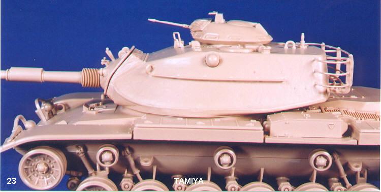
(23): shows gap between gun mantlet/dust cover joint, which may possibly be fixed with lots of filing. This shot also shows the molded on stowage bin handles on the upper hull.
(24): turret right side and cupola detail, no lift rings given for cupola.
(25): overall view, right side. Two-piece lower hull gap is apparent.
(26): overall view, left side.
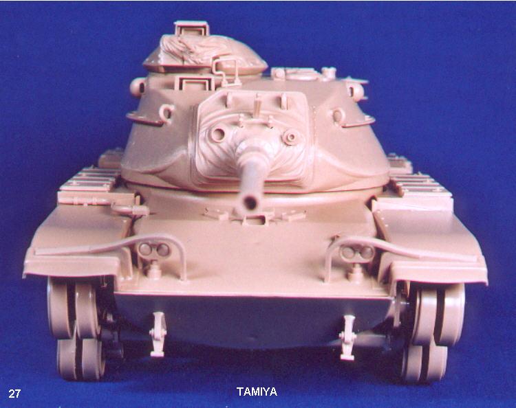
(27): front view Tamiya kit, sans tracks.
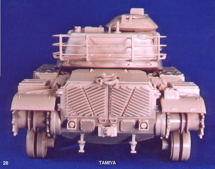
(28): rear view, lower attachment points of rear turret stowage bin will need some attention.
Academy kit:
-Similar fit problems as Tamiya, identical construction.
-I thought all the pieces were in the box to build the M-19 Commanders cupola, but the Blazer kit is missing the E sprue which contains the sight cover and flap on top of the cupola. Fairly easy to scratchbuild, I robbed parts from my USMC kit for this article, since I will put an Urdan cupola on this one eventually.
-Only kit with detail on front side of cupola mantlet (C5). Good photo of this on the back cover of Concord's M-60 book.
-Turret doesnt fit very well on ring - loose fitting and rear bottom part of turret interferes with the engine deck. May have to build up turret ring with .020 styrene.
 |
 |
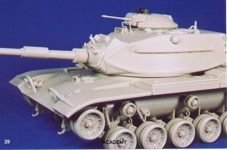
(29): again, a poor joint around the mantlet area. Also visible is a molded-on fender support and the separate fender stowage bin handles.
(30): a good view of the detail on the side of the cupola gun mount. Only the Academy kit has this detail.
(31): overall right side of model. Turret fits oddly on the hull ring: rear part of turret sits on engine deck.
(32): overall left view.
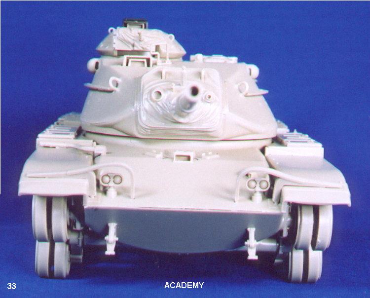
(33): front view, headlight guards need a little work to fit properly.
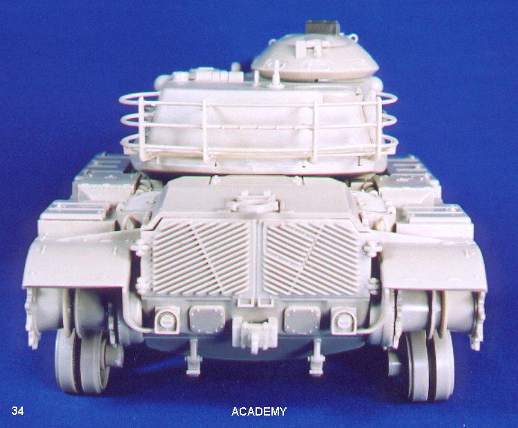
(34): rear view, better tail light detail, curved dust skirts provided.
Esci Kit:
-Also requires filler between upper/lower turret joints.
-Mantlet fit is poor, gaps need filling.
-Bustle bin much harder to assemble separate bottom rails tough to line up.
-If you are building this as the Israeli version, the turret mounted .30 cal crew weapons and mounts are very basic and need replacing.
 |
 |
 |
 |
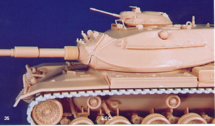
(35): darned mantlet gaps! Barely visible are some casting numbers to the left of the drivers hatch.
(36): cupola has lift rings, but no detail on the right side of the m.g. mount.
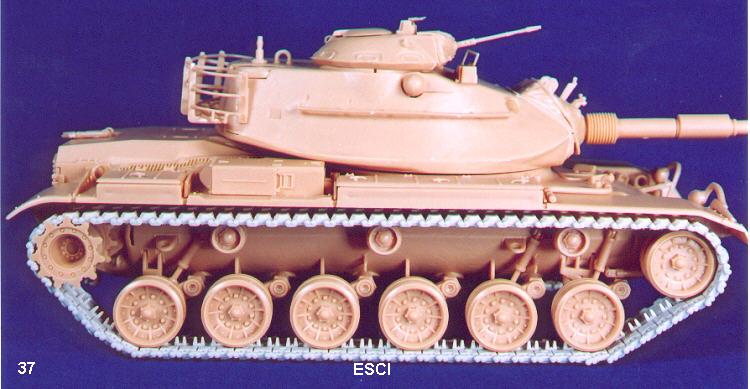
(37): overall right side view. Note the sink marks on the sides of the fender stowage bins.
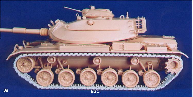
(38): overall left side view. Visible are the side-loading air cleaners. Also note that the turret stowage bin seems to angle up at the back (possibly due to my inattention during construction?)
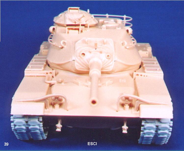
(39): front view, headlight guards also need work where they attach to the hull. Main gun sight seems under-size.
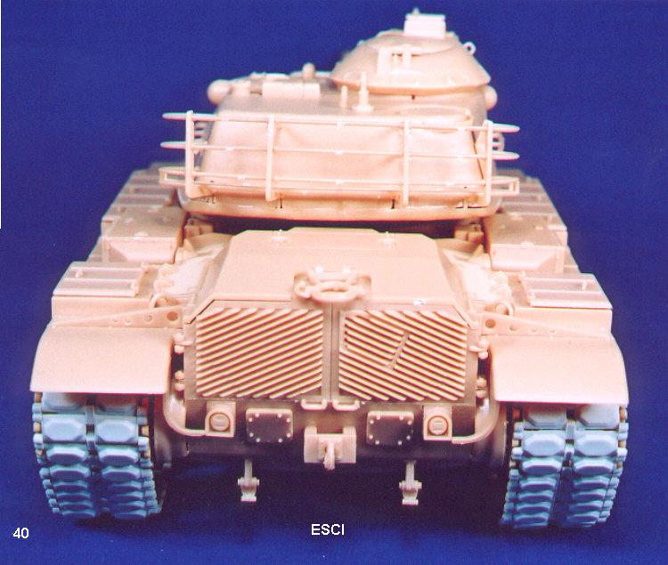
(40): rear view, separate fender supports evident here. Turret stowage basket supports need filling where they fit into the turret.
Conclusion
Well, look at the photos and be the judge - they all look like M-60A1's! Personally, I prefer the Esci kit for its lower hull and road wheels. If you don't mind a little work, the Academy kits are good too, while the Tamiya kit would be my last choice with its 30-year-old hull. Obviously, it will depend on what accessory/version you want to do as well (with dozer, USMC ERA, or Israeli Blazer ERA and/or Mine Rollers). Ideally, I would use the Esci kit as a basis, and add on Academy parts for the details (cupola, add-on armour, attachments and crew kit). For all kits, I would recommend using AFV Club's track sets.
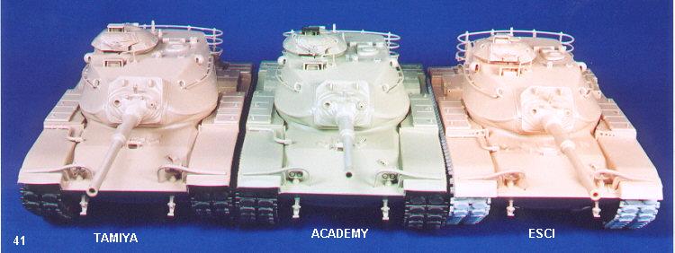
(41): the three kits side-by-side. From left to right: Tamiya, Academy and Esci.
(42): front ¾ view of the three.
(43): rear view; note that the Esci kit (on the right) sits slightly lower.
(44): upper rear view.
The Real Stuff
 |
 |
 |
 |
(45): a photo showing how the front suspension arm/idler damper attaches to the front suspension arm. None of the kits accurately portray this. Also note the bolt heads on top of the bumper stops. This is from an M-60A1 at The Tank Museum in Bovington, England.
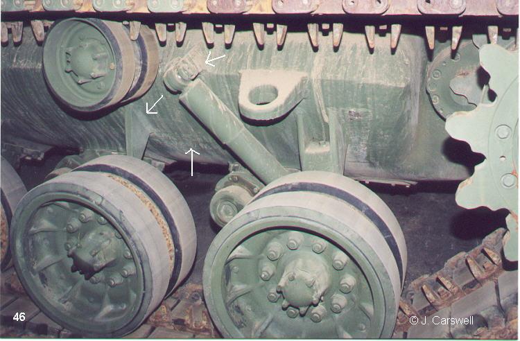
(46): in this photo we can see the attachment bolt on the upper end of the shock absorber. Note also the shape of the prong just underneath the return roller compared to the kit representations. It may not show up in the scan, but the lower hull has a cast texture to it. There are casting numbers just under the prong.
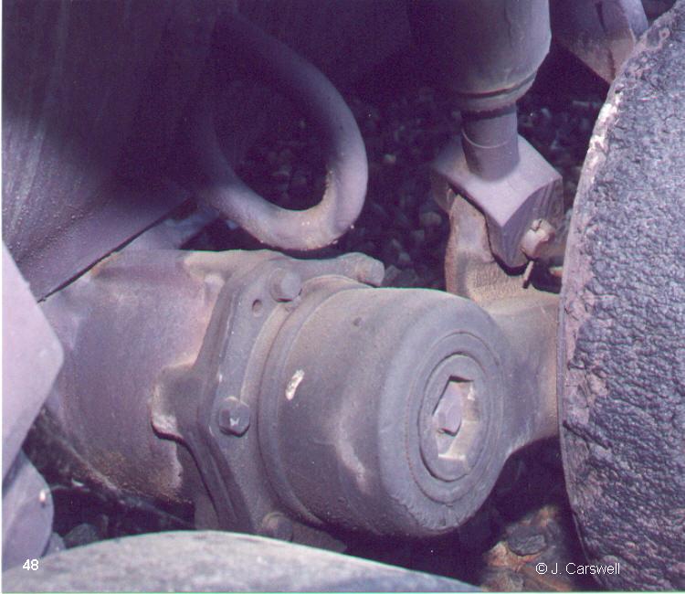
(47 & 48): how the shocks attach to the suspension arms. This is from the M-60 on Aberdeen Proving Grounds Mile of Tanks in Maryland. Im not 100% sure A1/A3s are like this, but I would guess they are.
 |
 |
 |
 |
(49 & 50): rear hull of A.P.G.s M-60 illustrating how the grill doors interlock with the upper hull overhang.
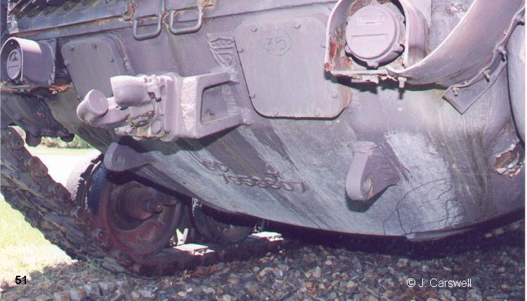
(51): lower rear hull detail of M-60 showing casting numbers and marks.
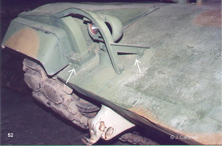
(52): this is how the headlight guards should look.
 |
 |
|
 |
 |
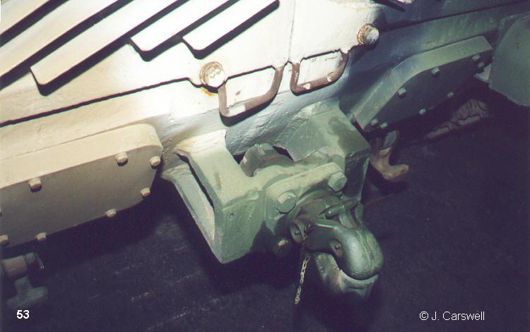
(53): tow pintle hook detail.
(54): rear hull details: hinges, fender support, also note how upper engine cowl attaches to lower hull.
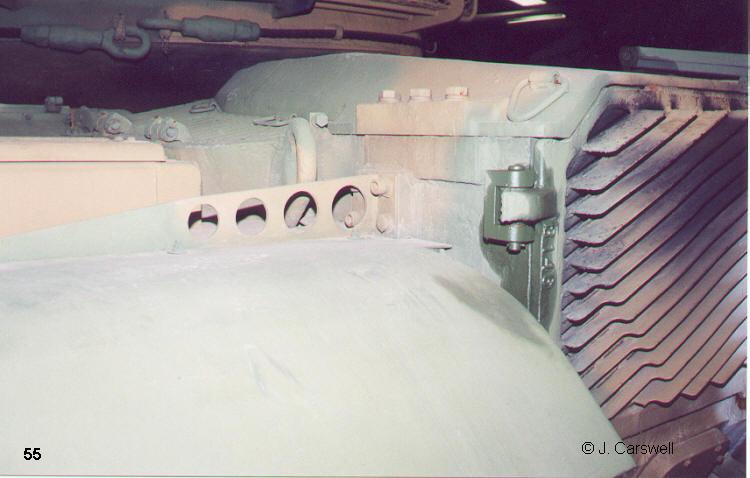
(55): dust skirt extension, tail light detail.
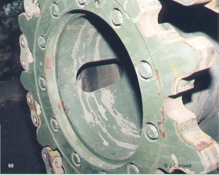
(56): shot of mud clearing hole in drive sprockets. There are three of these (120 degrees apart), and note they are not perfect ovals, one end is wider than the other.
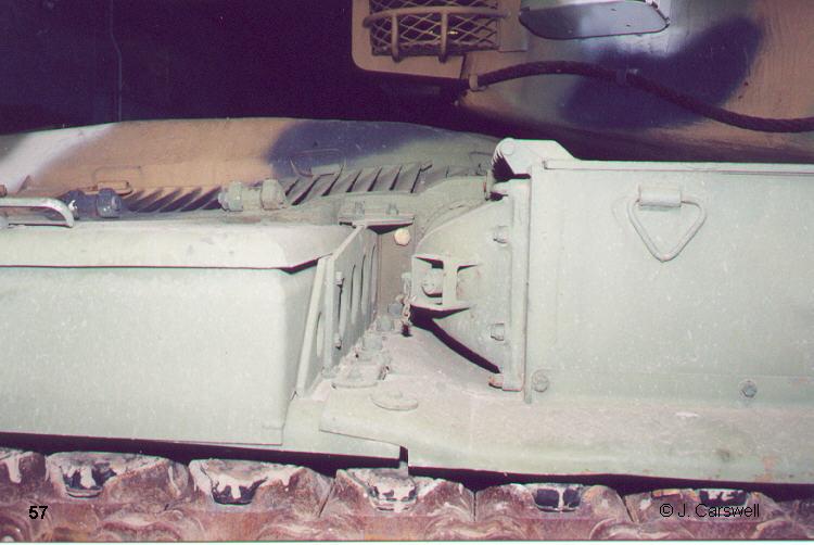
(57): check out the valve thingy on the air cleaner. Also fender support and fender joint.
References
M-60 Patton In Action, Squadron/Signal #23, Mesko.
M-60, Concord #1027, Green and Stewart.
USMC Firepower, Concord #1011, Debay.
Verlinden Modeling Magazines, Vol. 1, #4 and Vol. 2, #1.
Steelmasters Magazine, #42 and #44.
Additional M-60 Accessory and Conversion bits (of past and present)
AFV Club T-142 and M-48 Chevron style track sets.
Eduard Photo-etch sets.
Verlinden M-48/M-60 update set.
Verlinden Israeli Blazer ERA set.
AEF Designs - Numerous detail/conversion kits for US and Israeli M-60's.
CMD Early M-60, M-60 turret.
Lo Models M-48/M-60 accessories.
MR Models: Drive Sprockets for Israeli M-60 (Merkava track) Suspension Detail Set (Includes steel road wheels).
Royal Models detail set for M-60A1/A3 mostly photo etch.
And Im sure theres a few other things I forgot or dont know about!
| |
|
Home |