A Tale of Two Panzers
|
Revell’s 1/72 scale Pz IV
Introduction
I’d been considering modelling a vehicle in a winter whitewash finish for some time as it wasn’t something I’d tried before. Similarly I found the idea of a destroyed vehicle appealing. So with the release of two PzIV variants from Revell along with several aftermarket accessory sets, these ideas resurfaced. The kits
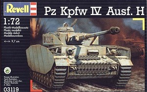
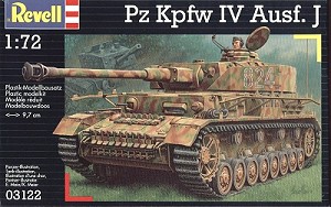
Revell’s Pz IV kits are without doubt amongst the best small scale injection moulded kits currently around. Two versions are available – the Ausf H and Ausf J. Both are based on the same set of common sprues with some additional parts provided for the Ausf J. As with most armoured vehicles, the Pz IV underwent numerous changes during its production lifetime and it appears that the Ausf. H is a late version whilst the Ausf. J represents an early/mid production vehicle. The following sections of the article concentrate on the common features of both kits. Scale I believe the kit generally scales very well to 1/72. I compared it to scaled down plans from the Panzer Tracts series (#4) that deals exclusively with the Pz IV. I also took a series of measurements from both the plans and kit. For those interested these are listed in the Appendix at the end of the article. Aftermarket accessoriesThe kits have been the focus for several aftermarket detailing sets, almost rivalling some of their 35th scale brothers for quality and quantity. The following is just a brief survey of some of these accessories. PartThis Polish company produces several sets aimed at both the Revell and Hasegawa kits. All of these contain an impressive amount of parts, representing even the smallest of details. During the writing of the article, further sets were released specifically for the Ausf J, as most of those listed here are for the Ausf H version.
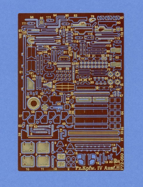
General detail set (Ausf H)
Although this set is for use with the Ausf. H, most of the parts can also be used on the Ausf. J. It contains an incredible amount of parts considering the scale. The only real criticism I have of this set is that some of the items aren’t well represented using photoetched parts. This particularly applies to many of the tools and other items that simply aren’t flat in real life. Still, it is an excellent set and most of it is very useful, although I would only recommend it to someone with previous experience of working with etched part Fenders
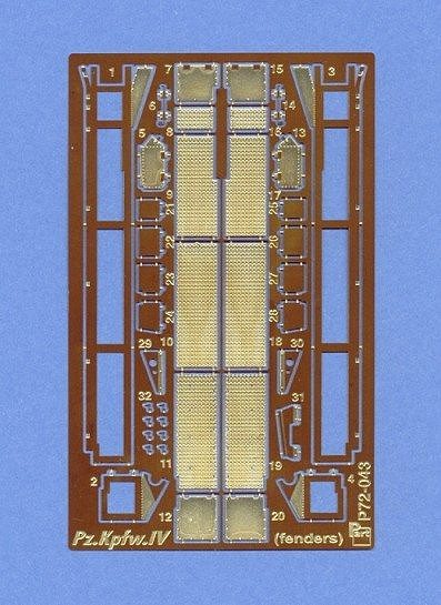
This contains complete replacement fenders but not the tool clasps that are fitted to them (these are provided in the general detail set). This set is particularly useful as the Revell fenders have moulded on tools. It also allows damage to be added very easily be careful bending, twisting or puncturing of the pieces. Use of the set requires careful removal of the plastic fenders moulded to the kit’s upper hull. Overall, this is another excellent detail set from Part and greatly enhances the kit.
Schuerzen set (Ausf H)
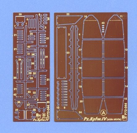
This set consists of both the turret and hull schuerzen panels and the associated support brackets. Be prepared for some stressful modelling if you buy this set, as the resulting assemblies are both fiddly to construct and quite fragile. I encountered some problems with the hull brackets and rails. In reality, the rails have an inverted L-shaped cross-section, but Part provides each one as 2 flat pieces that are simply glued together in an overlapped fashion. Whilst carrying out some test fitting using the photoetched brackets, I also found that the rails fit slightly too closely to the hull as provided. Although I have some reservations about the set, the schuerzen panels themselves are well made and the overall turret assembly looks very convincing when finished. ExtratechExtratech of the Czech Republic provide etched sets and more recently engines and other resin accessories for small scale armour. The sets discussed here are tailored towards the Hasegawa kits but they can also be used on the Revell ones with some minor modifications. I was also able to compare these sets to some 1/35th scale items. Of course, these aren’t primary reference sources, but it was an interesting exercise.
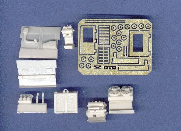
Engine set
This consists of several well cast resin parts for the engine compartment and engine itself, along with a small fret of photoetched parts for some of the smaller details. Overall I’d recommend this set as it only requires a few additional details for an interesting addition to the kit. Note that if used for an Ausf. J version, the supplied auxiliary power generator should not be used – this should be replaced with an extra fuel tank. Driver’s compartment
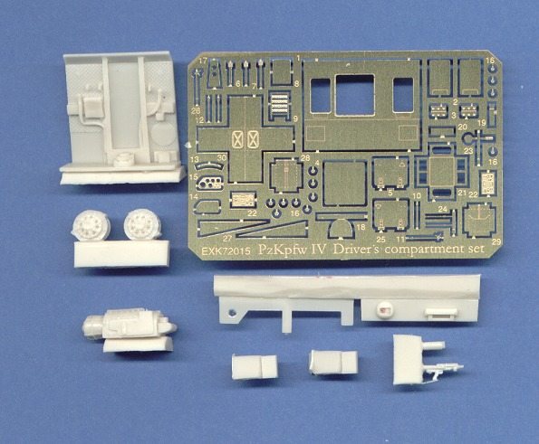
As with the engine compartment set, this set contains a mixture of well cast resin parts and a photoetched fret for the smaller details. Some details are missing however, such as the drive shafts connecting the sprockets to the transmission housing. The instructions suggest that these be added using plastic rod, but they do require a little more detailing. I also think the overall shape of the main transmission housing doesn’t look 100% correct. However, it is still a very useful basis for further improvement. Jadar turned barrel
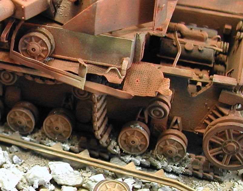
Even small scale kits can now be fitted with turned aluminium barrels. Armo of Poland market an L/48 for the Pz IV, along with barrels for several other kits. The L/48 barrel is very well made but unfortunately the version I received represents the earlier, and shorter, L/43. This may just be a mistake with my sample or a general error - I’m not certain. The barrel would have made a good replacement for the kit piece as it is well machined and just requires the addition of the kit muzzle brake. It can however still be used on some of the earlier versions. Construction – Ausf J Lower hullI began construction with the lower hull and running gear. As I’d planned to place the finished model on a small base, some of the suspension units were sliced of the hull sides and replaced at slightly different angles to give the impression of a vehicle on rough ground. The wheels and track were glued to the model as per the instructions and no assembly problems were found. Lower hull front
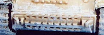
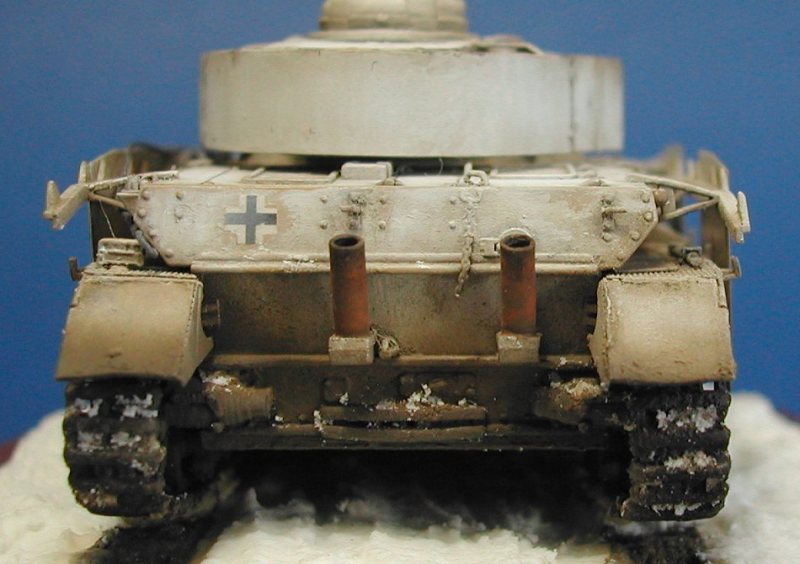
The kit towing brackets were detailed and the spare track retainer added. The kit supplies the front towing brackets as solid pieces. I sliced each part into two halves and removed the central portion. A hole was drilled through the brackets and a short piece of wire inserted. A piece of spare track was attached to the hull front and a retaining bracket added (this not being supplied in the kit). Hull rear
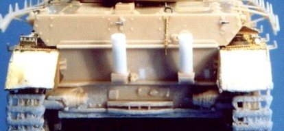
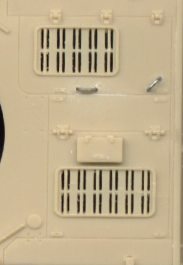
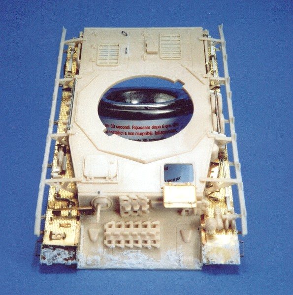
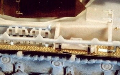
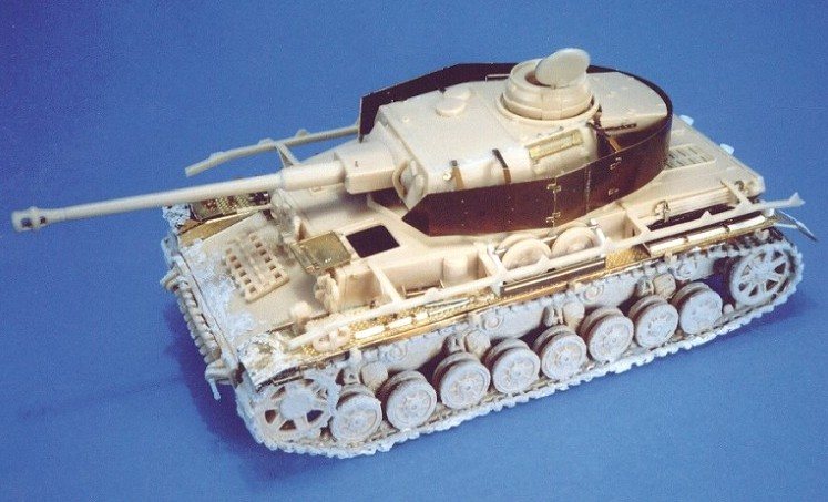
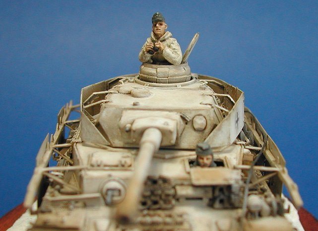
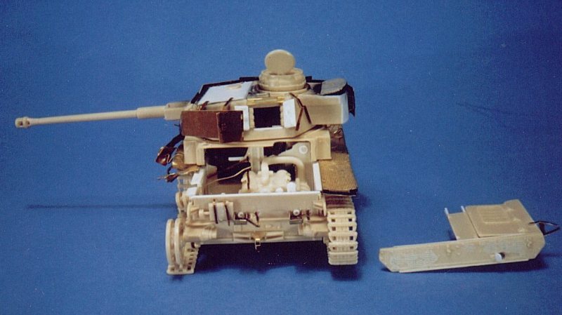
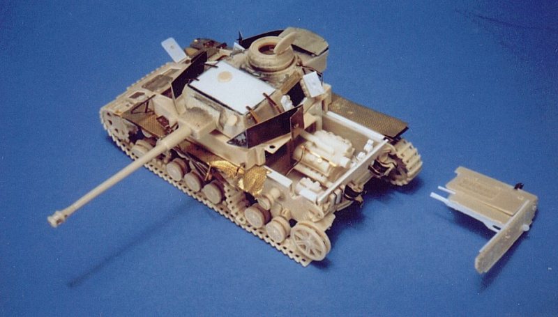
The kit flammentoeter mufflers were replaced. Later version Ausf J vehicles are characterised by the flammentoeter mufflers fixed to the rear hull plate. The kit includes these but comparison against the scale plans showed them to be both too short and thin. The locating holes for the kit parts are in the wrong places so I filled the holes with small strips of plastic. I made replacement mufflers using plastic rod of a suitable diameter and drilled the ends out. I used two modified kit parts (number 10) as the base for attachment to the hull. These are provided for the Ausf H version but should be used for the J also. Upper hullAs I was planning to use the Part photoetched fender set, the first task involving the upper hull was the removal of the plastic fenders. I was careful not to damage the fenders themselves too much as I wanted to use some of the moulded on tools later on. The glacis plate was also removed leaving just the upper portion of the hull piece. I used the Part photoetched pieces for the driver’s hatch as this was to be left open. Wire grab handles were also added to the engine deck.
Engine deck grab handles were replaced with wire. Part provides several pieces for the air intakes fitted either side of the hull towards the rear. These went together quite well, despite being a bit fiddly. The resulting assemblies were then immediately attached to the hull before I had a chance to crush them! The photoetched fenders were then fitted. Again, no problems were encountered and the procedure just involved a bit of care and patience. I also added a bit of damage to the fenders by gently bending and distorting them. On the real vehicle the front mudguards are hinged, so I didn’t fit the left side one and I attached the right side piece in a "flipped up" position. Fender details
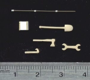
Work then began on adding the numerous brackets and fittings on the fenders. The Part detail set provides all the clasps and brackets along with most of the tools as photoetched pieces. I used the brackets but I’m just not convinced by the realism of photoetched tools. I removed some of the tools supplied on the kit fenders in order to reuse them and replaced the rest with homemade items.
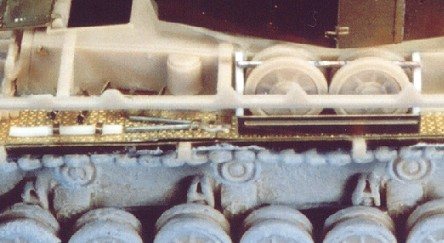
Right fender details. The spare track rack was replaced and the individual links taken from a second kit.
Left fender details. Some of the tools were removed from the Revell fenders and the rest were homemade. Some of the tools were left separate ready to be attached after painting. This was helped by leaving some of the clasps in an open position - allowing them to be carefully closed after painting.
Some of the moulded on tools were removed from the kit fenders.
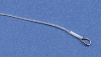
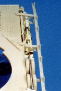
A tow cable was made using fine grade nylon thread. The hoops at the ends were made using wire bent into shape. These were then attached to the cable using thin collars made from plastic tubing stretched over a flame – in the same manner as stretching sprue.
The cable was made using wire, plastic tube and nylon thread. Hull schuerzen
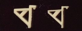
The overscale kit schuerzen rails were thinned.
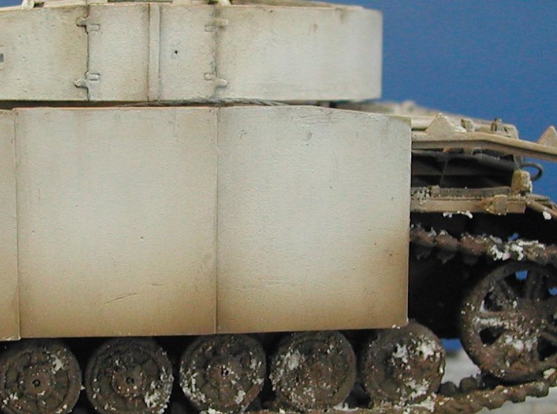
I had originally planned to use the Part schuerzen set that includes the brackets, rails and schuerzen for both the hull and turret. Ultimately, I used the kit brackets and rails (suitably thinned) for the hull, and the photoetched items for the turret as I wasn’t too impressed with the etched rails.
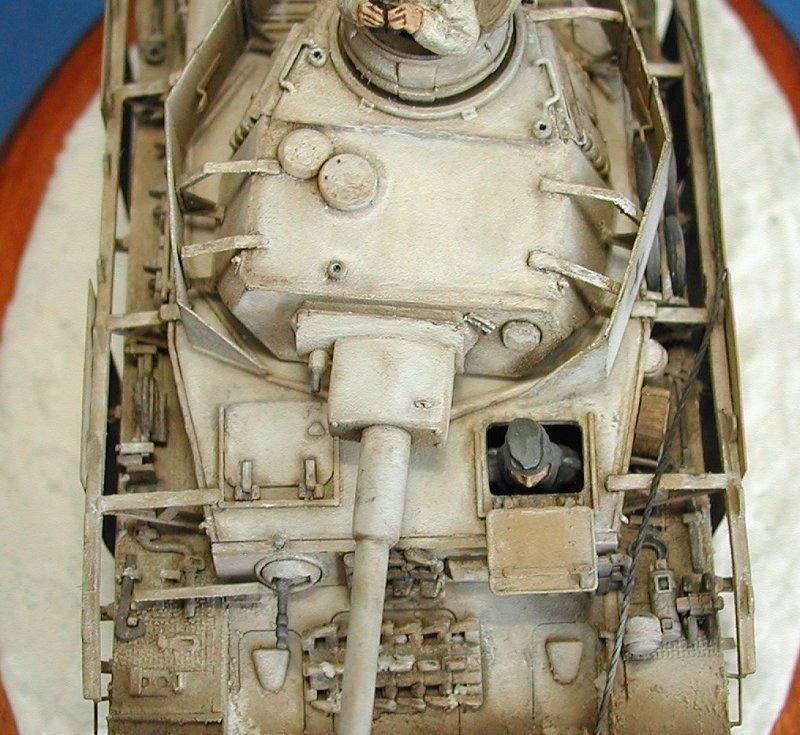
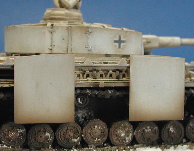
The kit schuerzen brackets are overscale and were thinned down. The hull schuerzen were then left separate from the completed model ready for painting. Turret
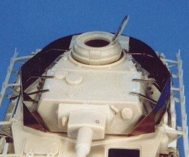
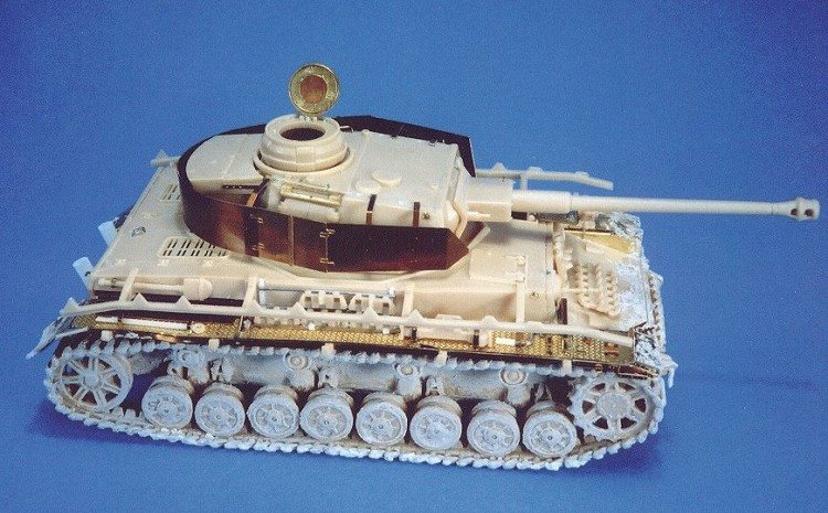
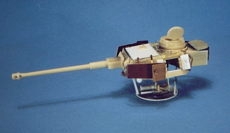
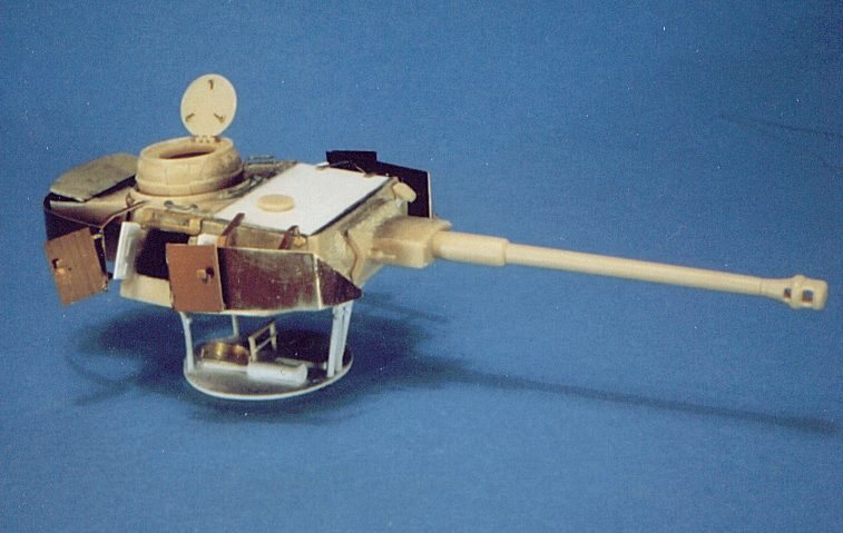
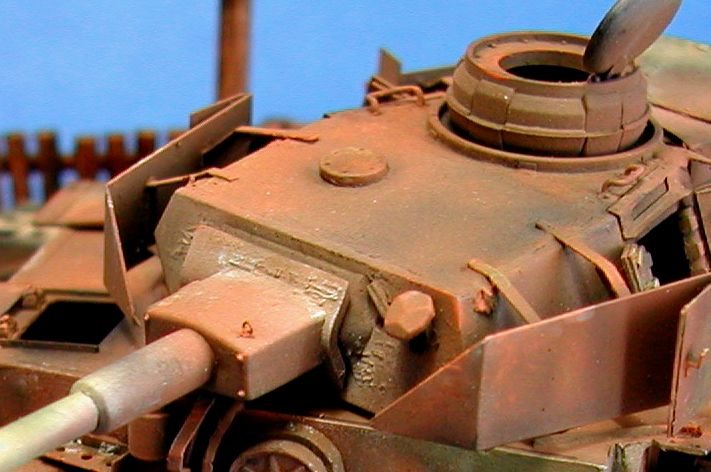
Completed turret with photoetched schuerzen.
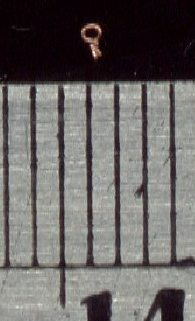
The basic turret assembly was very straightforward. All the fittings and details were added before I attempted to add the schuerzen, as these would be quite delicate. Some of the PART etched items were used along with a couple of other small homemade details such as the grab handles either side of the turret roof. Then came the tricky bit - attaching the schuerzen to the turret. I used superglue gel for attaching the brackets and panels as, although it dries quickly, it does allow a small amount of repositioning. I also used a very small amount of 2 part epoxy glue, which was applied around the joints between the turret, brackets and schuerzen to add some extra strength. The smallest detail I added was the small hoop situated on the main gun. This was formed from very thin fuse wire and is less than 1 mm in diameter.
The smallest detail part added – a tiny wire hoop.
Painting and finishing
All the paints used were from the Humbrol range and applied using an airbrush.
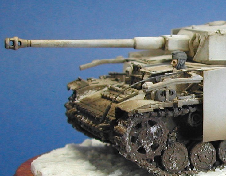
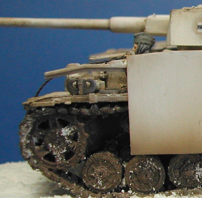
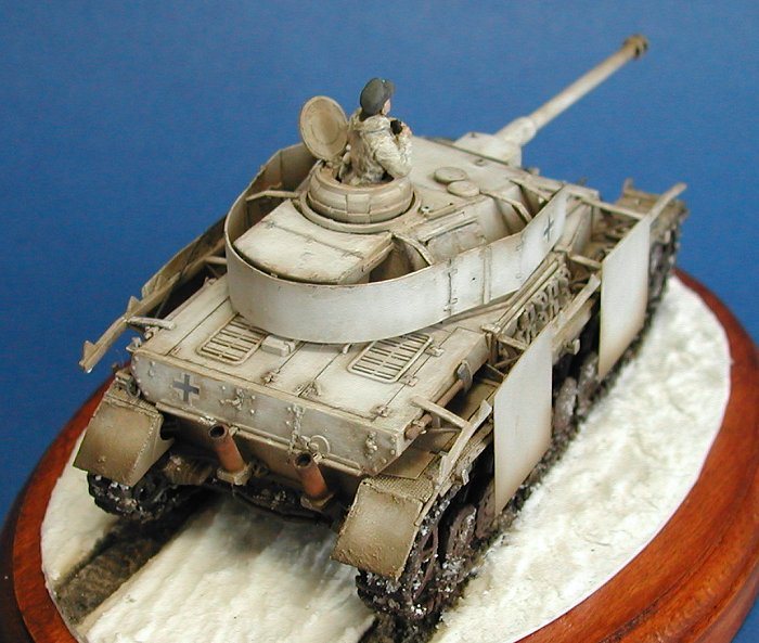
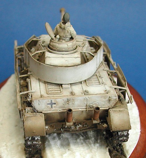
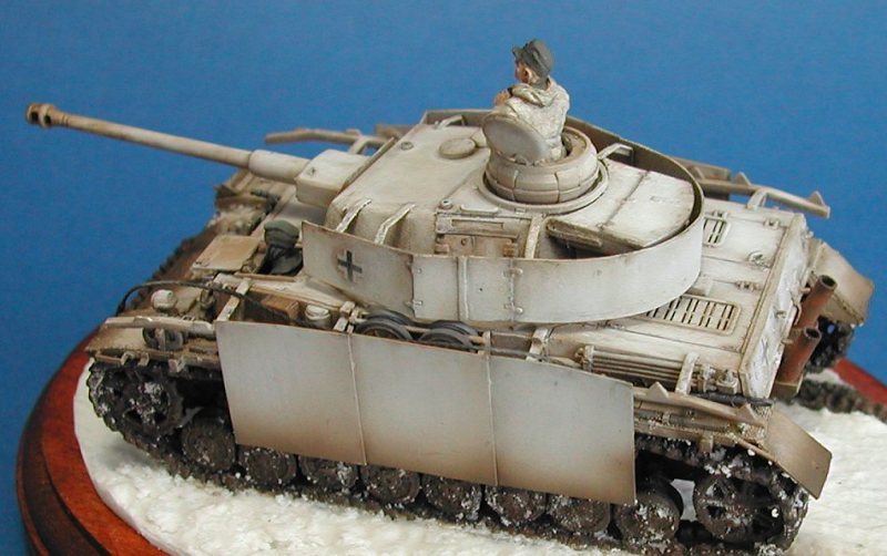
· A light grey undercoat was applied to the whole model. · The model was given a base coat of Desert Yellow (94). · The kit markings were applied. · A coat of Johnson’s Klear acrylic floor varnish was brush painted over the model to give the base colour a tough coating in preparation for the next stage. · Pure white was airbrushed over the entire hull and turret and left to dry for just a few minutes. · A small brush dipped in thinners was used to gradually remove the white from certain areas of the model. Mainly the edges and areas expected to take more wear such as the hatches. · After thoroughly drying for a couple of days, an overall dark brown wash (Dark Earth (29) and black mix) added further griminess to the finish and helped to accentuate some of the details. I applied it to a section of the model at a time and then wiped the excess of with a small cloth. · A dilute mix of thinners and black oil paint was applied locally to the details. · A very dark brown colour was sprayed over all the running gear and lower hull sides. · Small scratches were applied with a sharp pencil.
The various smaller details - mainly the tools and figures – were then painted. The figures were installed and the upper and lower hull parts glued together. The small base was kept simple and is simply composed of polyfilla and this was also added in patches to the wheels and track of the model. Small patches of gloss varnish were applied to certain areas of the lower hull to simulate wet mud, where for example the snow had partially melted. The crew are white metal figures from the AB range and were also painted using Humbrol enamels. For the skin tones, Radome Tan (148) was used as the base colour with various shades of darkened Brick Red (70) applied as washes.
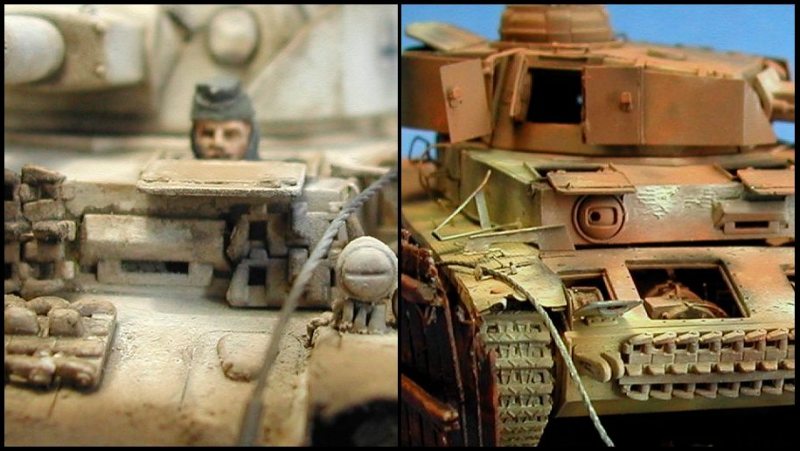
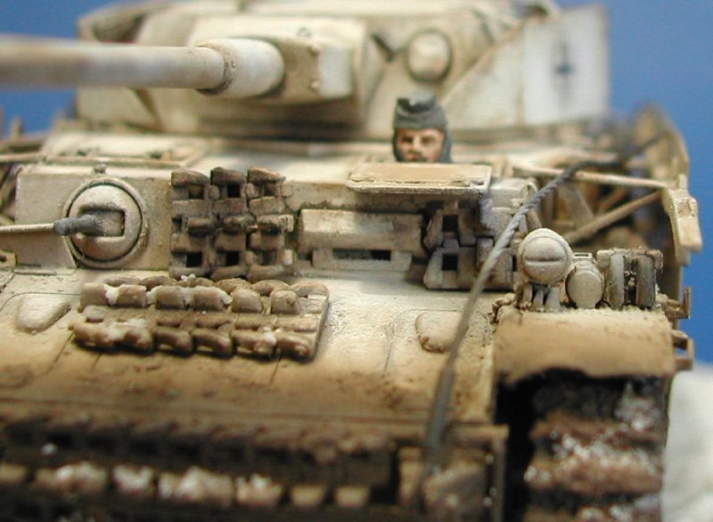
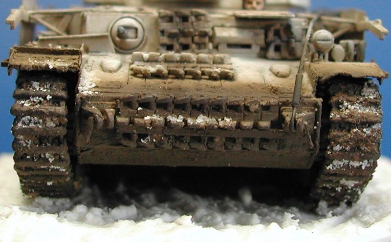
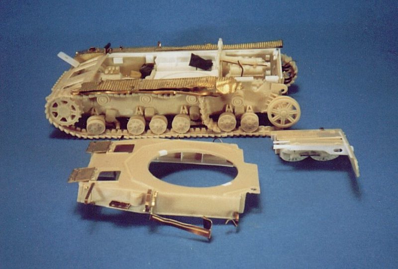
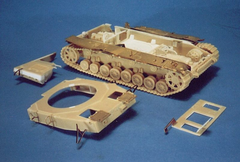
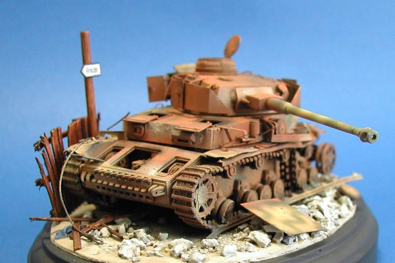
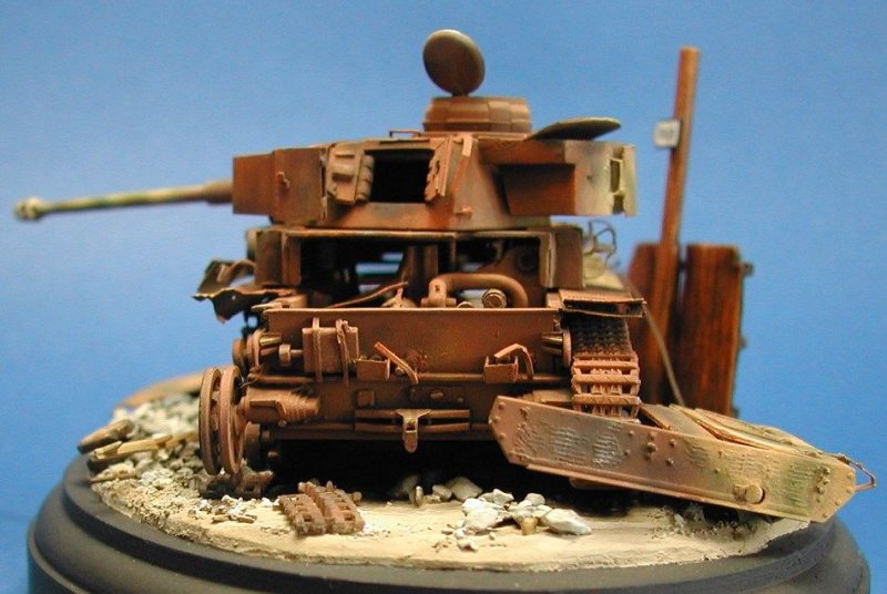
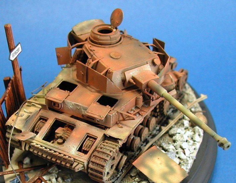
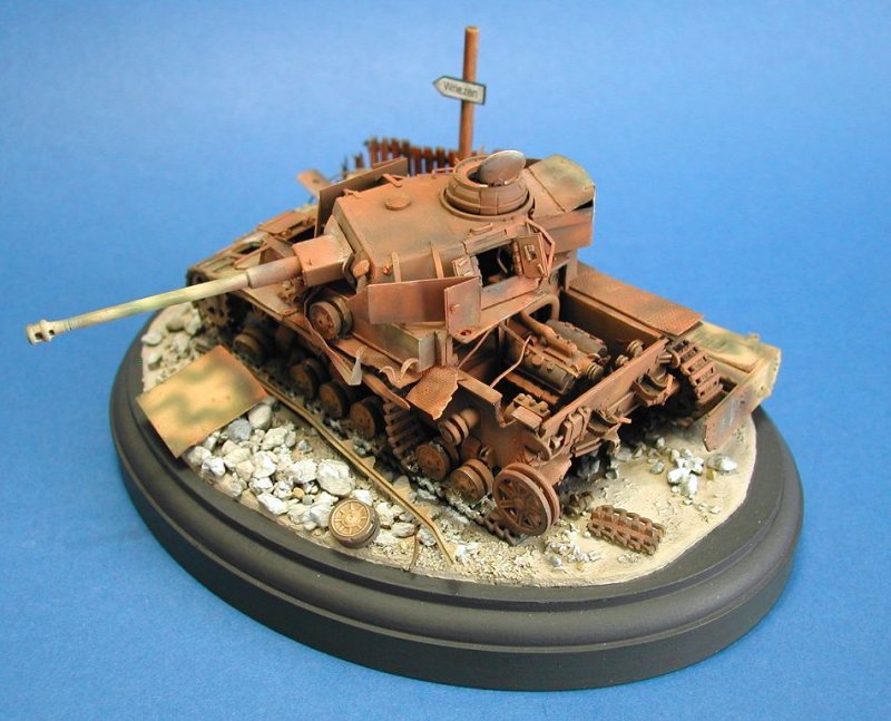
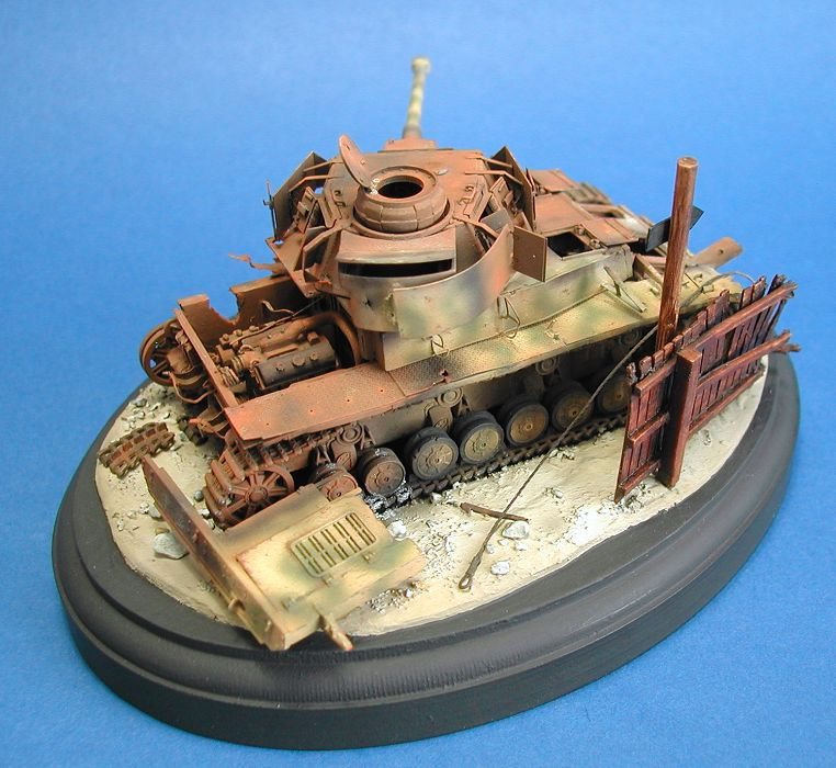
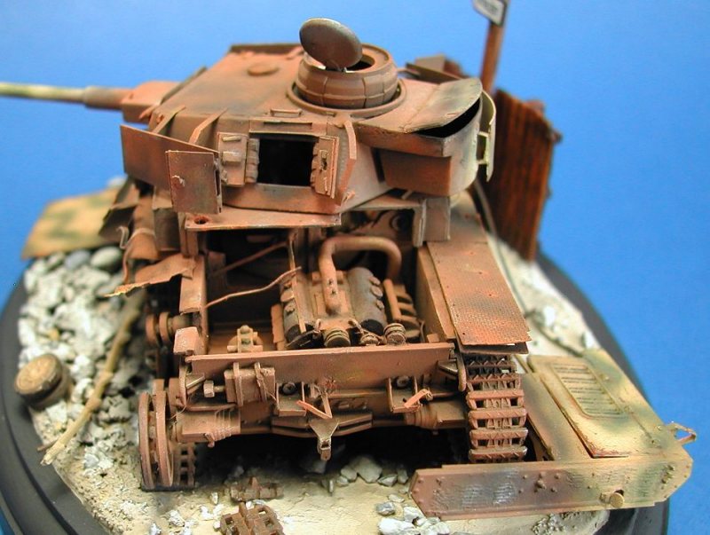
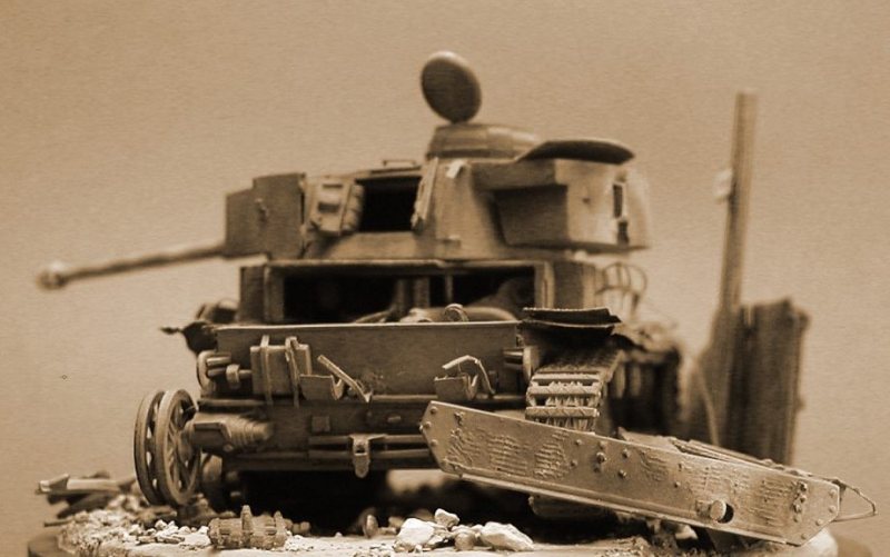
Construction – Ausf H This was quite a contrast to the Ausf J due to the fact that I was modelling a destroyed vehicle. Detailing the complete steps to make it would make a long article in itself so the following is just an outline. As I wasn’t planning to model a specific vehicle, I used ideas from several photographs of different knocked out vehicles. I wanted to model a vehicle that had been hit several times, with the main impact being on the left side of the engine compartment. There had then been an explosion in the engine compartment following this and the vehicle had started to burn. Hull
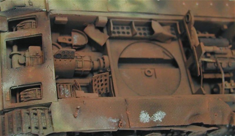
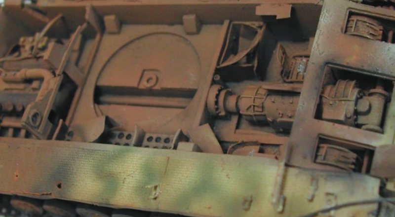
The Extratech interior sets were used as the basis for the driver and engine comparments. I added a fair degree of detail as all the hatches were to be left open and the engine deck removed, but certain areas that wouldn’t be seen were slightly simplified. There are currently no fighting compartment sets available, so this was scratchbuilt using plastic and brass sheet, plastic strip and rod along with wire of various diameters. The main reference was the excellent CMK resin interior (for the Tamiya 1/35th scale kit) along with photos from various reference books. I removed the outer portion of each roadwheel on the left side of the hull to represent the rubber tyres being burned off. The track on this side was also damaged by gently bending the link and length parts provided in the kit and draping them over the return rollers. The plastic fenders and glacis plate were then removed from the upper hull piece. The Part photoetched fenders were assembled and attached to the hull, along with some added damage. As with the Ausf J, the tool clamps were taken from Part’s general Pz IV etched set, with some of them being left off and the others fixed in an open position. The glacis plate was thinned down from the underside and the transmission and brake hatches were opened up. The engine deck and access panels were also removed, separated and thinned down. Small patches of zimmerit were added to the hull front using Milliput putty. I wanted to model the vehicle as if most of the zimmerit had burned off but with small areas still left intact. Whilst soft it was textured with a home made zimmerit tool. Turret
The turret interior was fully scratchbuilt. I thinned the insides of the turret, which are extremely thick. I then cut out the turret side hatch openings and the side hatches themselves were scratchbuilt. The turret roof and the rear stowage bin rear was replaced with thin plastic card and the lid itself was separated and thinned. The Part photoetched turret schurzen were then added. Unfortunately most of the turret interior can’t be seen on the finished model unless the turret is removed – but I had fun building it!
Painting and finishing - Ausf H
As with the Ausf J, I used Humbrol enamels for finishing.
· The whole model was given a coat of black that acted both as primer and as a base colour for pre-shading. · Several patchy rusty brown oversprays were applied over the black. It was applied slightly more heavily around the exposed edges and upper surfaces of the model, leaving the appearance of darker shadowing around the lower areas and adding some tonal variety. · Remnants of the original paint work (dark yellow and green camouflage) were applied by airbrush, mainly around the lower right side of the vehicle. These areas escaped the fire that burned the rest of the vehicle. · Small areas were painted with a fine brush using black, red, orange and yellow enamels. These were then immediately blended in using thinners. · Finally small amounts of black pastel were applied to represent areas blackened by the smoke.
The base was made using a couple of thin layers of Milliput putty covered in fine sand. Some cat litter was ground up into various sizes and sprinkled over a thin layer of white PVA glue to form the rubble, rocks and stones. The fence was taken from a model railway set. The small sign post is just textured plastic rod, with the sign printed on a laser printer and backed with plastic strip. Finally some items from the vehicle were attached to the ground such as spare wheel, damaged track and other small items using twisted photoetched parts.
For a bit of fun, I messed around with the colour and contrast of one of the scans in an attempt to give it the look of an old black and white photo.
AppendixThe following table lists a series of measurements taken from the Revell kit and the 1/35th scale plans in the Panzertracts book. The first column of values are taken directly from the plans. The second column are based on these values converted to 1/72 scale and the third column lists the corresponding values on the kit.
References A number of reference books were used during the project. For these particular projects, I found that the first 3 listed were the most useful.
Panzerkampfwagen IV Panzer Tracts No. 4T. Jentz and H.L. Doyle
Panzerkampfwagen IV Achtung Panzer No. 3
Panzer IV Ausf. H/J Kagero PhotosniperW. Hryniewicki, R. Danilczuk, S. Jablonski
Panzer IV and its variants Schiffer Military History W. Spielberger
PzKpfw IV In Action (Armour number 12) Squadron SignalB. Culver
Panzerkampfwagen IV medium tank 1936-1945 New Vanguard 28 B. Perrett, J. Laurier
Panzer IV Schiffer Military HistoryH. Scheibert
Panzer IV (lang) Schiffer Military History H. Riebenstahl, H. Scheibert
Panzerkampfwagen IVAFV Profile 43W. Spielberger
Bellona Military Vehicle PrintsSeries 6 |
|
|