Home >
Gallery >
Britain > Building a Full Resin
Resicast Sherman ARV Mk.I
Part One - Construction |
|
Building a
Full Resin Resicast Sherman ARV Mk.I
Part One - Construction |
Resicast,
1/35 scale |

|
by Paul Chatfield
|

Resicast's 1/35 scale Sherman ARV Mk.I is available online from Mission Models
Introduction
With the ever-increasing amount of resin conversion kits and some
really nice full resin kits becoming available, I thought I would
offer some suggestions, based on my own experiences, on building a
resin kit.
Manufacturers such as Resicast, Accurate Armour, Plusmodel and
Cromwell models all now offer full resin kits of a nice range of AFV
subjects. Very often these subjects are unavailable in traditional
injection moulded plastic kits.
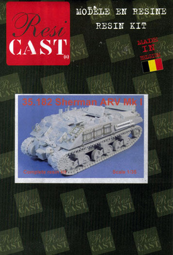
For this article I’m going to be using Resicast’s Sherman ARV MkI
full resin and photo etched Brass (PE) kit. Resicast also offer this
vehicle as a conversion kit, for the Dragon Sherman, which is
considerably cheaper than this full kit, but does require the
purchase of the Dragon base kit too.
 Pros
and Cons of Resin Kits Pros
and Cons of Resin Kits
Resin kits are not for everyone
and have their advantages and disadvantages. I’ll now try and give
an honest list of the pros and cons of resin kits.
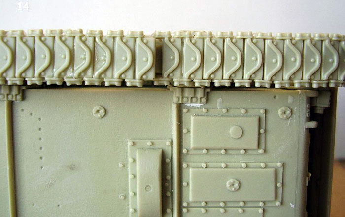
To begin with the advantages of resin; Surface detail is usually
much finer than an injection kit. For example on the Resicast
Sherman; weld seams are correctly shown raised, foundry casting
numbers are visible all over the model, the surface has a definite
cast texture and detail is cast on both sides of parts. Resin can be
used to cast much finer parts than injection moulding and some of
the detail is stunning. Due to the different technology used resin
parts carry no ejector pin marks so there are none to fill or sand
off. Being limited run, most kits offer a significant advantage in
accuracy over mass produced kits. This also means the purchase of
aftermarket correction or detail kits is rarely necessary. (I have
never bought after market tracks for a resin tank) Resin
manufacturers tend to do kits of less mainstream subjects, so you
get some really different and interesting subjects.
Now the disadvantages of resin kits; Firstly for most people cost.
On the whole, resin kits cost more than injection kits, sometimes a
lot more. This can be balanced somewhat by the fact that you don’t
need to buy aftermarket parts. Resin requires different tools. You
will need Razor saws for separating parts from pour stubs and super
(crazy) glues for attaching parts. You may also require 2 part epoxy
glues in some cases. You will need dust masks and extractors when
sanding or sawing resin. (But you should already have an extractor
in your paint booth). Some parts can suffer from air bubbles that
need filling and sanding. Fine flash may require clean up on smaller
parts. Some parts can warp or distort, although dipping in warm
water and straightening will easily remedy this. The instruction
sheets from some manufactures leave a lot to be desired and the
modeller often needs to use references to find the correct location
of parts.
Building the Sherman ARV
Building Shermans can be a bit
confusing, due to the large range of variations and modifications
built throughout its operational life. Resicast do an excellent
range of resin Shermans of different types such as M4A4, M4A1,
Direct vision hull, Duplex drive as well as the ARV. Luckily
Resicast have done their Sherman research thoroughly and you can be
pretty certain that all parts are where they should be for the
particular type of Sherman you are building.
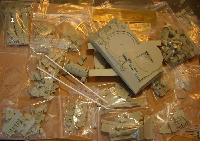
On opening the box you are faced
with a mass of parts; large resin mouldings for the hull, bags and
bags of smaller detail resin parts, Resin tracks, PE frets, plastic
rod, string, copper wire and little lenses, along with an
“instruction” booklet.
Lower Hull and Tracks
As with most armour kits construction starts with the lower hull and
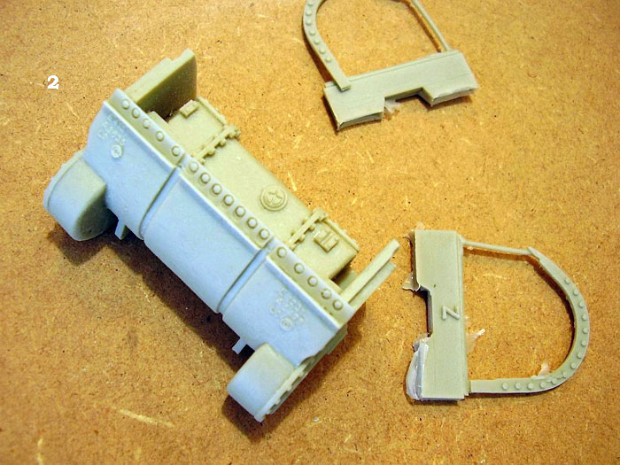
suspension. The detail on the Resicast parts is superb. Most of the
lower hull is one large casting. It carries not only the external
details but also details on the interior surfaces. (Resicast offer
another separate kit to fit out the inside of the M4A4) The lower
front hull containing the transmission is cast as a block, again
with all interior details shown.
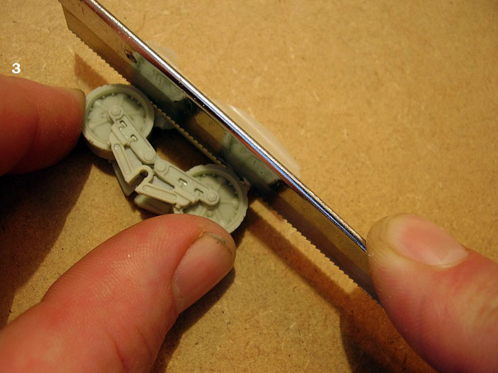
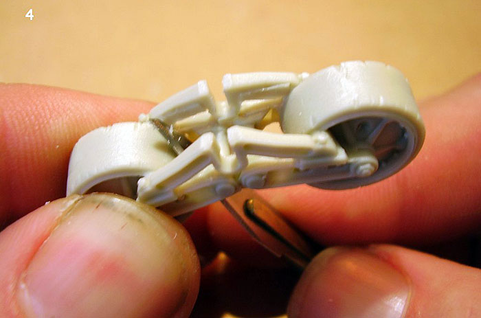
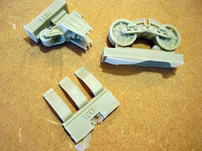
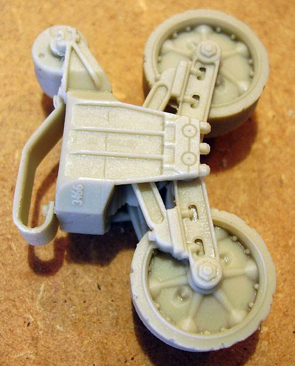
The road wheels and suspension
need separating from their casting blocks with a razor saw and
some “webbing” cleaned out of hollow areas. I used a sharp Swann
Morton No 11 blade to clean out these areas, and then sanded them
smooth. Each set of wheels and suspension requires only three parts;
wheels mounted in swing arms, main suspension body and the top track
guide. . Once tidied up and assembled detail is superb, the wheels
click into place without the need for gluing.
Click the thumbnails below to view additional images:
With all the road wheels made up I
attached them to the hull sides, taking note, which sets fitted to
which side. This being a limited run resin kit, instructions aren’t
laid out in a step-by-step system, as you would expect with Dragon,
Tamiya, Italeri Etc. The instructions consist of a (long) list of
parts and numbers and a series of photocopied photographs of a model
during construction. This means the modeller has to study the photos
carefully for parts positioning. A good photo reference of an actual
vehicle is also very helpful. To add complication, on this
particular kit, some part numbers/letters are duplicated due to the
fact that this kit is a combination of Resicast’s complete M4A4 kit
and a conversion kit (to ARV spec) that also fits Dragon’s Sherman.
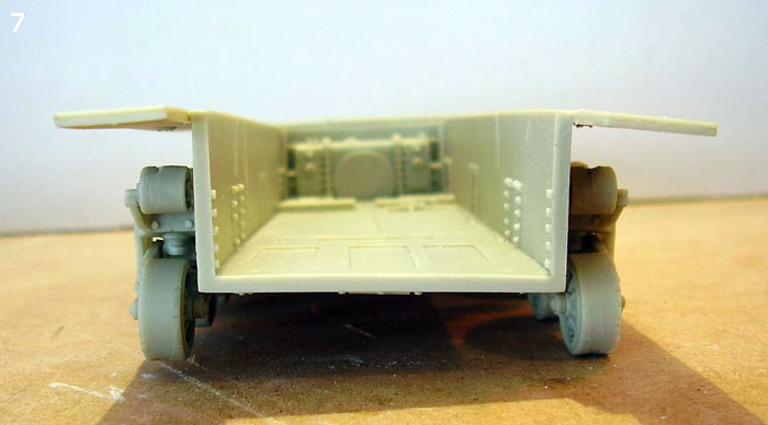
With the wheels on the Hull it became obvious that the lower hull
was a little warped. The left rear road wheels didn’t touch the
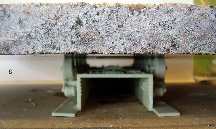
ground at all! With resin, this is not that hard to remedy. I took a
bowl of hot (not boiling) water and submerged the whole model in it
for 3-4 minutes. Then placing model on a firm flat surface I placed
a heavy object (in this case a piece of Granite slab I had hanging
around) on the wheels to push them into line. I left this for around
30-40 minutes to cool and set back in place. Once the Granite was
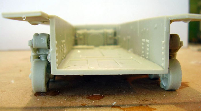
removed the model was stood back on it’s wheels and every thing now
touched down as it should. (Still dripping!).
Click the thumbnails below to view additional images:
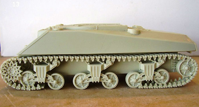
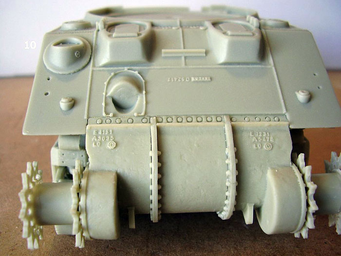
Next to be attached were the rear
engine plates and doors. Attached to these are the rear idlers,
which complete the build of the running gear. The entire top hull is
one casting. To make this fit a little bit of “tweaking” was
required. The left hand sponson bottom just refused to sit in its
channel, under the sponson. I marked the area, which was a problem
and sanded it back until a good fit was achieved. Constant checking
is needed here to make sure you don’t take too much away. With this
done the upper hull slipped into place easily and the fit around the
front, to the transmission block is virtually perfect and something
even the very best mass-produced kits would struggle to equal.
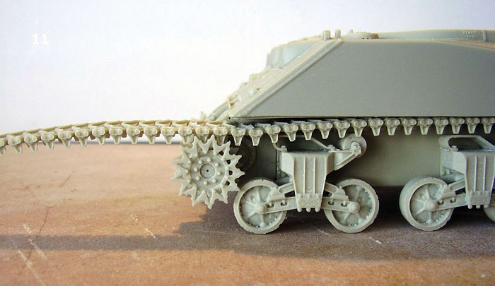
The final part of the lower hull
construction was the tracks. On most injection kits I would buy
aftermarket tracks, usually individual metal links that take an age
to build. With this kit I didn’t have to bother, because Resicast
provide very nice resin tracks. The tracks are provided in several
different lengths of links. The night before I needed them I made up
two lengths of track, one for each side. Each length was enough to
cover the top run and tuck underneath the road wheels at the front
and the back.
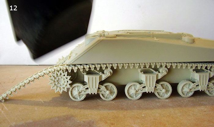
With the tracks totally set they
were placed over the upper part of the running gear, with a good
over hang at the front and the back. Now for a very unusual
modelling tool, a hair dryer! With the tracks in position a hair
dryer, set to hot, was aimed at the over hanging portions. Within a
few seconds they started to droop. When they were fully “sagged” the
tracks were fitted around the front sprocket and the rear idler
wheel, then the model placed flat on the workbench. After a couple
of minutes the tracks had cooled and set into their new shape. Care
should be taken with the hair dryer as it softens all resin that it
comes into contact with and delicate parts can easily warp. With
everything cooled and set, adding more links between the ends of the
fitted track finished off the tracks. They were not completely
joined, as the tracks will be taken off of the model for painting,
the final join can be done when all painting is finished.
This method of track building is
so much quicker than individual links and is well suited to the
tight “live” tracks fitted to Shermans. I’ve never used a resin
replacement set on tracks with droop, like Panzers or T-34s, and I’m
not sure how well it would work with them.
Click the thumbnails below to view additional images:
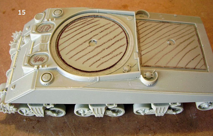
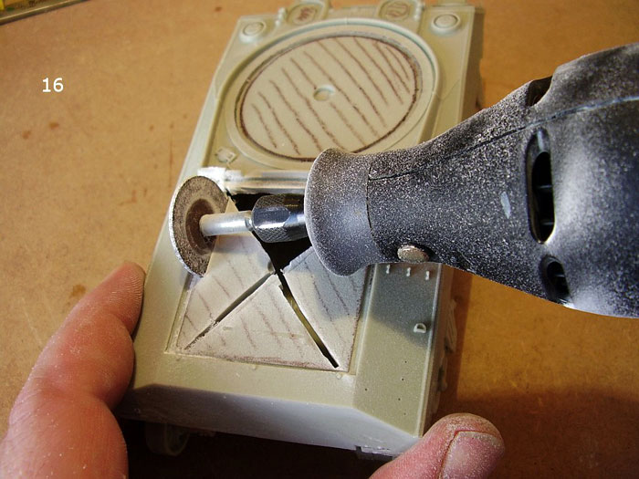
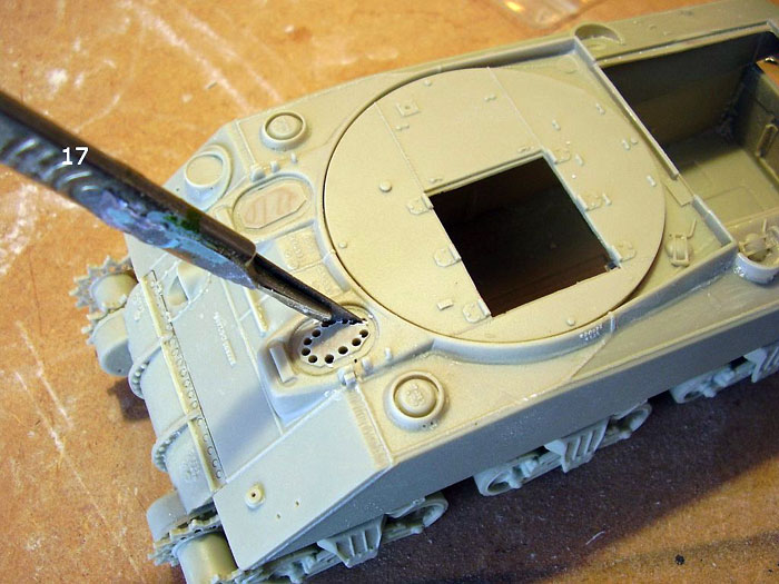
Upper Hull and Fittings
The upper Hull, as mentioned previously, is one solid casting. This
means the holes for the engine deck covers, the turret plug and the
driver hatches need cutting out. Before I started cutting I marked
out the areas I needed to remove. To cut out the main parts of the
bigger holes I used a Dremmel motor tool fitted with a cutting disc.
This is a VERY dusty process and an extractor and dust mask are a
must, as is eye protection. I cut the holes slightly smaller than I
required and finished them with files and sanding sticks. For the
smaller crew hatches I used a different much less dusty technique. I
drilled out a series of holes inside the line of what I needed to
remove then cut through them with a sharp blade.
Click the thumbnails below to view additional images:
The hole was then trimmed almost
to size with the blade, and then the last little bit was done with a
small file.
Now it was time to start fitting the multitude of hull fittings that
the ARV featured. I started with the “standard” fittings, lights,
lifting hooks, intakes and the like. After this came the specialised
fittings of the ARV. There are literally dozens of parts to be
fitted and the instructions are not that clear as to the exact
placement and positions of some parts. This is where good reference
photographs really help. I have a photo of an actual ARV in the
field that I want to base this model on, so some parts were placed
with reference to what I could see in the picture and not what’s in
the instruction booklet anyway. As with most resin kits there are no
tabs or holes for fitment of the parts they are simply glued to the
hull.
The majority of fittings are in resin with just a few brackets and
support frames in PE. I won’t bore you with a long list of parts
fitted or the order in which I fitted them. All I will say is, on
this model, it takes a long time (I estimate over 15 hours of work).
Personally I enjoy this part of the build, although towards the end
it did start to drag and I just wanted to get it done so I could
start the paintwork. I had no particular difficulties, although
getting some parts in position was fiddly. Resicast supply the parts
for a full lifting jib and (for a change) a nice diagram complete
with dimensions, to show the positioning of parts. As I’m building
an ARV in the process of towing a Panzer I didn’t build the jib up,
but rather, fitted the parts in their stowed positions. Plastic rod
and resin parts are supplied for this. One part of the kit I
replaced was the cord supplied to represent the tow cables. The real
thing would have been heavy-duty wire, woven to make a cable. The
vehicle in my photo had one cable draped over the front end. I
always feel that cord is to soft and floppy to use for this and
hangs all wrong on the vehicle, so I replaced one of them with
copper cable from Karaya. This gave a much more authentic looking
stiffness to the cable. Other cables are wrapped around hooks on the
hull in a large loop and the supplied cord was fine to represent
this. The kit’s resin end pieces were used, as they were slightly
sharper detailed than the Karaya items.
Due to the fact that I am following a photo of an actual ARV in this
build I had to make a couple of parts not supplied in the kit. The
kit does not have any track guards supplied with it, (The vast
majority of Shermans in the field had their track guards or “sand
shields” removed) but the ARV in the Photo has a full front guard
fitted on the right hand side. I considered leaving it off, but then
decided it could be easily built from Scratch. I didn’t have any
Scratch to hand so I used an empty Cider can instead. I find the
metal used on drinks cans is ideal for building little bits and
pieces of sheet metal, such as track guards, turret bins and the
like. It cuts easily and bends to shape with no problem. Try as I
might I couldn’t find a plan drawing of a Sherman with it’s Guards
fitted, so I studied what photos I could find and made a best guess
at the dimensions. Once made up and placed on the Model it looked
just about right and I was happy with it. I placed a piece of
Verlinden stowage on top of the fender, blended to the shape with
Squadron putty along the bottom.
At the back of the ARV is a box
with a telephone, to allow a crewmember at the rear of the Vehicle
to communicate directions to the driver. The kit supplied one of
these in the closed position. I wanted mine open, with a crewmember
talking to the driver, so I quickly made one up using more metal
from the can and a little plastic card. Finally with all PE fixings
attached a little Squadron putty diluted in Liquid Polly was used to
blend them to the hull. (This gives off strong fumes and good
ventilation is essential) You could also use Mr Surfacer for this
task, but I had none to hand.
The last part of the build process was to check over the model for
glue smears and any other areas that needed clean up before priming.
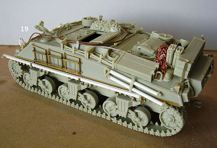
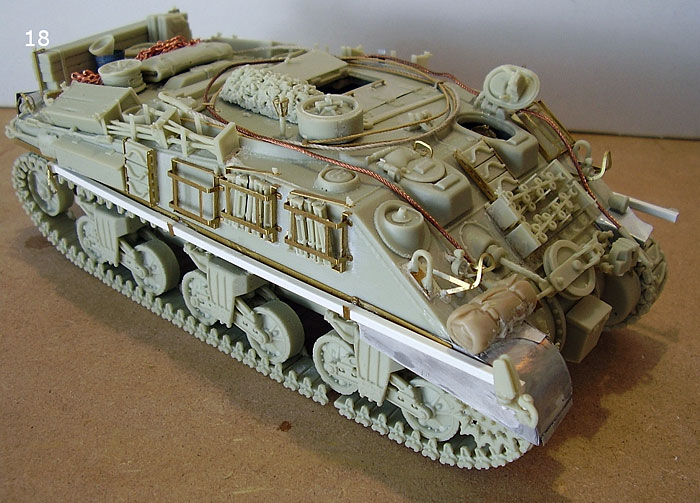
With every thing fitted the model
was literally bristling with surface features and looked pretty good
to me. Just wait until I get some painting and weathering done! That
will come in the second part of the article, which will concentrate
on painting, weathering and all the finishing touches and details
applied to this model.
This kit is quite a complicated affair and may seem intimidating if
you have never built in resin and PE before. I certainly wouldn’t
recommend it as a first resin project, but chose it for this
article, as it enables me to show most of the techniques and tools
required for a resin kit. Most companies do smaller, easier
subjects, such as armoured cars, which make ideal first tries at
resin. My first resin kit was a Humber scout car, from Accurate
Armour; it’s a nice little kit with fairly good detail and has resin
and PE parts. I would recommend that type of kit as a starting
point. Then once you have the feel of resin models pick something
more challenging.
I bought this kit from Panther models in the UK, through their e-bay
shop. I have been buying from them for about a year now and find
them totally reliable. The model cost £76.99, which is a lot of
money, but this is a lot of model with fabulous detail and no need
for any after market parts. You pay your money and make your choice.
That’s what I did and I’m satisfied with what I got!
Part 2, on finishing, will follow on in the near future.
Click the thumbnails below to view additional images:
Model, Text and Images by Paul
Chatfield
Page Created 15 September, 2006
Page Last Updated
15 September, 2006
|