|
|
|||||||||||||||||||||||||||||||||||||||||||||||||||||||||||||||||||
|
|
| Home > Reviews > German > Dragon Models Limited 1/35 Scale ‘39-‘45 Series Kit No. 6262; 7.5cm Pak 40/2 auf Fahrgestell Pz.Kpfw.II Marder II |
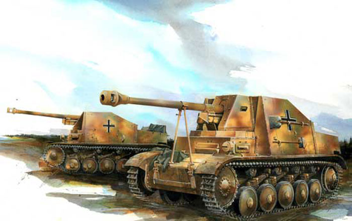
7.5cm Pak 40/2 auf Fahrgestell Pz.Kpfw.II Marder II
by Neil Stokes
Summary
| Stock Number and Description | Dragon Models Limited 1/35 Scale ‘39-‘45 Series Kit No. 6262; 7.5cm Pak 40/2 auf Fahrgestell Pz.Kpfw.II Marder II |
| Scale: | 1/35 |
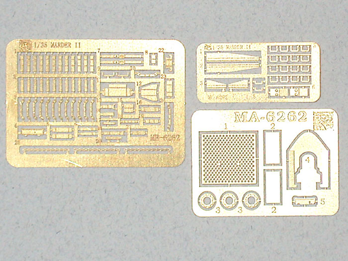
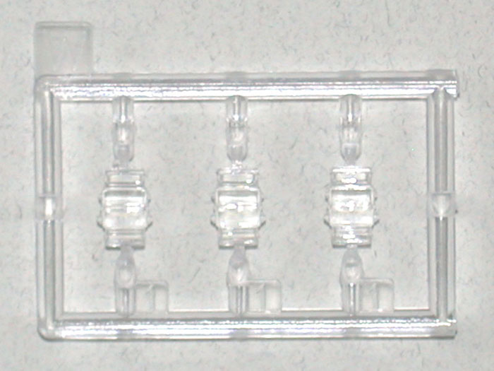
| Media and Contents: | 442 styrene parts on 22 sprues including 3 clear parts for the vision periscopes, 95 etched brass parts on 3 frets, plus a pre-formed brass shovel bracket and a turned aluminum gun barrel. Magic tracks. |
| Price: | USD$34.99 available online from Mission Models |
| Review Type: | First Look |
| Advantages: | Well engineered kit that is correct in the major details |
| Disadvantages: | Missing fuel filler cap; some confusing steps in instructions |
| Recommendation: | Highly Recommended to experienced modelers. |

Dragon's 1/35 scale Marder II is available online from Mission Models
FirstLook
The Sd.Kfz. 131 Marder II was one of the first Panzerjaeger vehicles to mount the 7.5cm Pak 40, though the Marder I using the captured Lorraine-Schlepper chassis appears to have beaten the Marder II into service by a mere month. The Marder II was armed with the 7.5cm Pak 40/2 L/46, with secondary armament of an 7.92mm MG34 and a 9mm MP38. The Marder carried 37 rounds for its main armament. Combat weight was approximately 11 metric tons. The vehicle had a crew of three: gunner/commander, loader and driver, who also operated the radio set.
Tom Jentz states in Panzer Tracts No.7-2 that a total of 531 Sd.Kfz.131 Marder IIs were built from July 1942 to June 1943. According to Tank Power Vol. I #209, the first 123 vehicles were built by Famo at their Breslau plant before production switched to the Warsaw plant. A number of the Marder II were converted from existing Pz.Kpfw.II chassis by Famo, MAN and Skoda.
There were also a number of vehicles - the quoted numbers vary from 30 to 75 - completed by Alkett in 1944 with the 5.0cm Pak 38 gun. Photographs and scale plans appear in Tank Power Vol I #209; see the References section at the end of this review. Thanks to Roy Chow for pointing this out.
The Kit
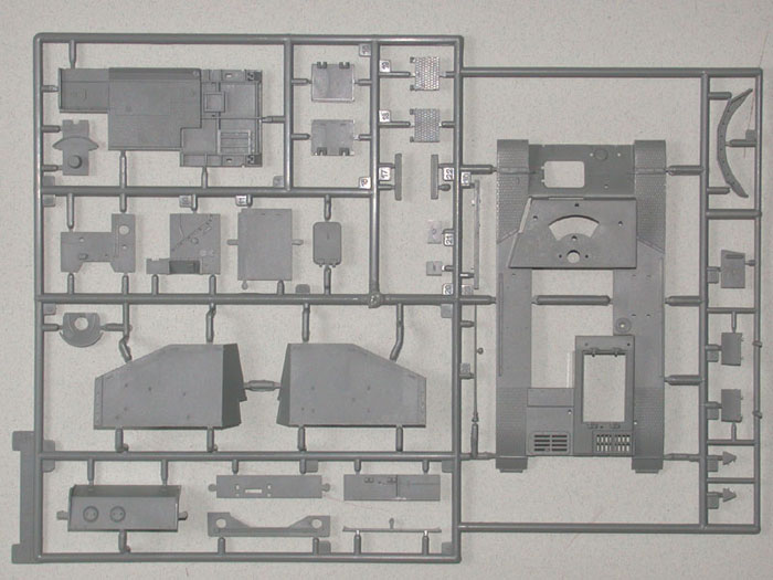
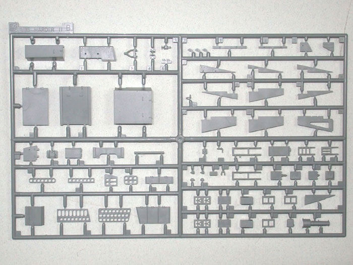
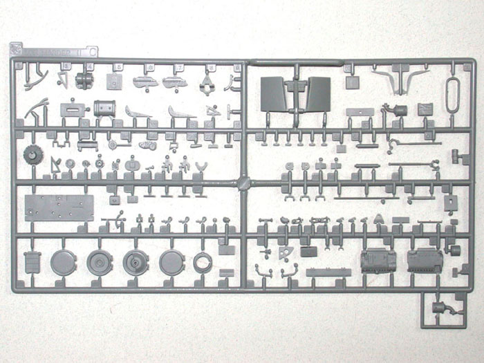
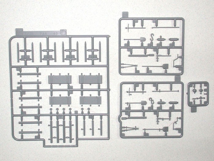
DML’s new kit is molded in the usual grey styrene, and contains some 442 styrene parts on 22 sprues including 3 clear parts for the vision periscopes, 95 etched brass parts on 3 frets, plus a pre-formed brass shovel bracket and a turned aluminum gun barrel. 19 of the styrene parts are marked “not for use”; these are extra parts from the Pak 40, the MG34 tripod in its unfolded configuration, additional personal weapons and some parts from the on-vehicle tools sprues. Two bags of “magic tracks” are provided, and these are handed for the left and right tracks.
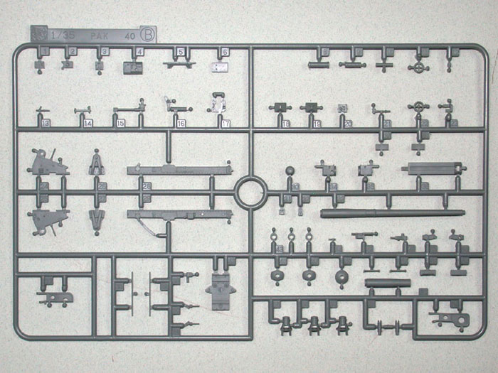
Note that there are two ‘B’ sprues; one is shown with a black ‘B’ in the instructions, while the other has a blue ‘B’. The black one contains superstructure and ammunition stowage parts. The blue one contains the gun cradle and other gun parts, and comes from the Pak 40 kit.
Click the thumbnails below to view larger images:
|
|
|
|
|
|
|
|
|
|
I took some quick checks of major hull, suspension and wheel dimensions, and these compare well with Hilary Doyle’s drawings in Panzer Tracts No.7-2, and with the plans in Armor Photogallery #9. There is some question about the length of the gun barrel since the plans in the two books differ somewhat; more on this later.
The instructions are in the usual fold-out format with exploded view drawings. The drawings are quite “busy”, though not so much as DML’s Tiger I and Pz.Kpfw.IV kits. Nevertheless, a good deal of care will be required during construction in order not to miss anything. Perhaps DML could consider breaking the construction down into a larger number of somewhat simpler steps; this would make life easier for everyone.
DML has chosen to depict a late production vehicle, as is evident from the details of the superstructure sides, rear ammunition stowage, tool stowage and so on. If you wish to model an early production version, you will need to make a lot of detail changes. Some of these are relatively simple while others, such as the early Fu.Spr.Ger. “d” radio set, will require additional parts from alternate sources.
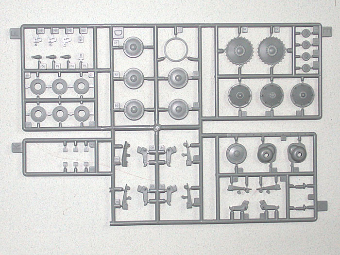
Assembly commences with the running gear. To begin with, the modeler is given a choice of three different idler wheel configurations; the first has the outer domed cap in place, the second has the outer cap omitted to reveal the bolt-heads and the inner domed cap, while the third has both caps omitted and the outer axle boss revealed. Check your sources for the vehicle you are modeling. A separate outer rim is attached to your choice of idler, creating the correct “channel” appearance. The idlers also have good detail definition on their rear faces, though there are four shallow ejection pin marks on the rear of each wheel. These should be relatively easy to clean up.
You are given two choices for the drive sprocket; the configuration with nineteen attachment bolts seems to have been more common on early to mid-production vehicles, while the reinforced configuration with three rivets between each pair of bolts appears most commonly on late production examples. These are attached to nicely molded final drive housings, to each of which three tiny styrene bolts must be attached. While this will produce a very nicely detailed result, the tiny bolts will require a steady hand.
The leaf-spring suspension is represented by separate parts for each leaf spring, the spring housing front plate and the axle arm. I recall Tom Jentz commenting once in a seminar that each of the leaf springs on the late Panzer II suspension had a different number of leaves, but DML has chosen to give us springs with all the same number of leaves. Correct this if you care – and if you dare.
The kit provides volute spring dampers for the first, second and fifth wheel stations, and simple bump stops for the third and fourth stations. This configuration is correct for a mid- to late production vehicle. Earlier vehicles had bump stops on all the wheel stations as was standard on the Pz.Kpfw. II. If you are really keen on building an early Marder, will need a second kit or you can try casting your own using the kit parts as a guide.
The road wheels have nicely rendered hub detail with the correct recessed bolts. The “Continentau” emblem is embossed on the rubber tires, as do the return rollers. Again, some quick work with a hobby knife will result in the correct “Continental” name.
The “magic” tracks are nicely done with only a very small molding pip in the center of the inner face on each link. A quick swipe with a file will rectify this. The instructions would have you use 99 links per side, though Panzer Tracts quotes the real vehicle as having 108 links per side.
At this point, the instructions also have you assemble the majority of the etched brass tool clamps; the instructions call for 10 but DML gives you 12 to allow for the one or two that always go into tweezer-launched orbit. The clamps are 3-piece assemblies that assemble in a similar way to Aber clamps. Note that the kit gives you option of using the etched clamps or using an alternate set of tools with integrally molded styrene clamps.
The rear plate contains separately molded access port covers, rear step, 2-part towing bracket with separate pin and etched retaining chain, and early Notek rear light. The access port covers have simple bolt heads instead of the correct wing nuts. These could be easily replaced with Model Kasten items.
The exhaust/muffler assembly is comprised of four parts plus an etched heat shield that will no doubt require annealing to get it to curl satisfactorily around the muffler. Lifting eyes and separate springs for the rear mud flaps complete the rear plate. Watch out for the springs (parts C37) since they are very tiny, project from the rear plate and are candidates for the all-devouring carpet monster. I would advise leaving them off the model until later in assembly.
Construction then proceeds to the driver’s compartment, where you get a fairly complete interior including seat, driving levers, pedals and transmission including the gear-shift lever. There are a couple of hoses and connections missing but these can be added from soft wire using photographs as a guide (see the References section at the end of this review). Be careful when fitting the cross-member (part A4) since the instructions are somewhat vague as to its location. Some trial fitting will be in order here.
The truly fastidious may wish to add springs to the rear of the driver’s seat but the better-informed (ie. those who have read this review) will wait since CyberHobby is shortly to release an etched brass update set for the Marder, similar to that for the Sd.Kfz.234/4, which will contain the springs among other items. More on the CyberHobby update set later.
The front plate sports some nicely detailed towing brackets and spare track stowage. The reinforcing brackets and inner attachment bolts for the final drive housings are also added at this point. I nearly missed these and thought I would have to add them from Grandt Line or similar sources, but they’re there.
Assembly now switches to the upper hull. The forward left-hand side of the driver’s compartment is molded separately (part A28) presumably to get better definition around the vision port. It appears to be a quite good fit with the upper hull, but the seam may require a little filling and sanding. The good news is that much of the join will be concealed by the superstructure – good engineering.
The front mud flaps fenders are separately molded and while the front edges are quite thinly rendered, the vertical inner faces will require some work with a hobby knife to thin them down. They, naturally, attach to the front fenders which, along with their supporting brackets, are integrally molded with the upper hull. The detail and tread plate pattern is nicely depicted but some modelers will no doubt wish to replace them with etched brass items from the aftermarket sets that are sure to appear for this kit.
Next we flip the upper hull over and commence work on the upper portion of the driver’s compartment, which is complete with vision devices, instrument panel and the large hull cross-member that passes laterally beneath the gun mount. Again the portion of the driver’s front plate immediately in front of his seat and containing the vision block is molded separately, so work carefully to minimize the seam cleanup required. The good news is that this part is covered on the outside by the driver’s front plate (part A3) so you only need to clean up the seam on the inside.
The underside of the upper hull’s aft end receives a nicely detailed firewall and air cleaner. There is a jack mounting bracket on the left side of the air cleaner, but no jack is provided. You can use the part from the Tamiya Panzer IV tools set if you wish to add this item. Be careful not to forget the drive shaft (part B50), which is shown in the little box below and to the left of Step 7. With care, it will mate up nicely with the aft end of the transmission. Again, test fit to avoid problems later.
One rather amusing omission is the fuel filler cap. The kit provides a nicely detailed rendition of the fuel filler port, but the cap itself is missing. Presumably DML mastered the kit from a vehicle such as the one at the Swedish Pansarmuseum at Axvall, which has the cap missing. I could not find a photograph of the fuel filler cap but I would presume it is similar to the caps on a Pz.Kpfw. IV. I have several spares from the DML kits so I plan to use one of those.
Now comes the fun stuff; the superstructure and its assorted hardware. The instructions get very busy at this point, so read and plan carefully. The superstructure sides have the tie-down cleats molded in place. The kit contains etched items to replace these, so if you want to use the etched items, you will want to shave off the molded cleats before you begin adding other details.
Note that the diagram below Step 8, which shows the MG34 being fitted into its bracket, needs to be completed before the central diagram in Step 8, which is really just a completed view of the right-hand superstructure side. When you get to Step 8, work from the bottom of the page upward for simplicity. As I say, DML really should consider breaking these instructions down into smaller and less confusing steps.
That said, the detail parts here are very nice. The flare box can be assembled with its lid open to show the flare holders inside, though the inner rack for the flares will need some thinning down for a true scale appearance. The 4-part vision periscopes and the fire extinguisher with its separate handles and retaining straps are all beautifully rendered. Even the reinforcement brackets for the joint between the front of the superstructure and the upper hull are provided in the form of delicate etched brass parts.
The kit provides a stowed MG34 with separate receiver cover, but curiously there is no provision to show the MG34 it its deployed position atop the right front superstructure. There is a hole in the upper right superstructure where the mounting bracket should go, but no bracket or other mounting hardware is provided. Wartime photographs indicate that the bracket is similar to the mounting bracket used to mount the MG34 or MG42 on the Marder III M, so if you really want one, you could probably use the bracket supplied in the Aber detailing set for the Marder III M.
You have two alternatives for the tool stowage on the exterior of both hull sides. The kit provides “bare” tools for use with the etched brass clamps and brackets, or you can use the tools with integrally molded styrene clamps. A good folding tool or a pair of flat-nosed tweezers will come in handy for the etched brass clamps.
The kit provides a pre-formed brass shovel bracket, but the truly detail-oriented should know that this is slightly incorrect in shape. Rather than the bracket attaching directly to the superstructure side as depicted in the kit, it is actually a shallow sleeve that is spaced out from the superstructure on a mounting bracket. If you care, you can modify the kit part with some shears and patience.
The FuG 5 radio in this kit is one of the nicest I’ve seen in styrene. Comprised of 21 parts for the two radio sets, their batteries, control box and mounting brackets, it rivals the best of the resin items I have seen. The purists will want to add some wiring between the units, but this should present no difficulty for the experienced modeler.
The kit provides alternative parts for the radio antenna mount. Both are the correct style mount for the FuG 5 set, but part A29 includes an integrally molded antenna while part C82 requires you to supply your own antenna from stretched sprue or wire.
Moving to the inner left-hand side, the kit includes a stowed MP38, vision periscope and two items (parts C15 and C19) whose function eludes me. Jentz does not mention them in the loading plan given in Panzer Tracts No. 7-2. Part C15 is presumably some kind of hose or cable, while I have no idea what part C19 represents.
Now the vehicle begins to take shape. Details are added to the glacis including upper towing cleats, spare wheel mounts and the driver’s front plate with a nicely molded two-part visor that can be positioned open or closed. The driver’s escape hatch (part A12) is also molded separately and can be positioned open if desired to display a little more of the interior than would otherwise be visible.
Many wartime photographs show tow cables looped round the base of the spare wheel mount on the glacis; indeed, the mounting brackets appear to be channel-shaped to facilitate this. The kit does not provide any tow cables, so you will need to source your own if you wish to add these to your model.
Note that the kit includes the Bosch driving light on the left front fender, but does not include a front Notek light or a horn as fitted to early/mid-production vehicles. If you wish to add these items you can use the ones from Tamiya’s Panzer IV Tools set.
I must confess that the forward gun travel lock is something of a disappointment, being very simply molded in two, albeit nicely rendered, pieces. Given the sophistication that DML displays in many parts of this kit, I expected a rather more detailed approach. However, this is something that can be easily rectified by the dedicated modeler with a little styrene strip and wire.
The engine hatches are molded separately and can be positioned open, but no engine or other interior detail is provided in the kit. This is not a criticism, merely an observation, and is an open invitation for one of the aftermarket resin manufacturers to produce an engine and compartment.
At this point (Step 11) the instructions would have you add the radio and superstructure sides to the upper hull, but I recommend leaving them separate until later. It will be far simpler to paint the interior at this point, then fix the upper and lower hulls together before painting the fighting compartment interior, superstructure sides, radio and gun (which is not built until Step 14) as separate assemblies. The vehicle can then be assembled and the fighting compartment masked before final painting, decaling and weathering. This will allow you to delay mounting those fragile render mud flap springs until the hull is closed up and you are ready to attach the mud flaps, thereby reducing the probability of losing those parts.
Steps 12 and 13 in the instructions deal with the ammunition stowage and the rear fenders. The ammunition lockers are multi-part assemblies that can be shown open or closed, and the kit provides multiple types of 7.5cm rounds that can be positioned in the stowage racks according to the modeler’s taste.
Do not forget the stowed axe on the rear of ammunition rack M. This is easy to miss on the crowded instruction sheet. Note that some wartime photographs show this item mounted upside down so check your references.
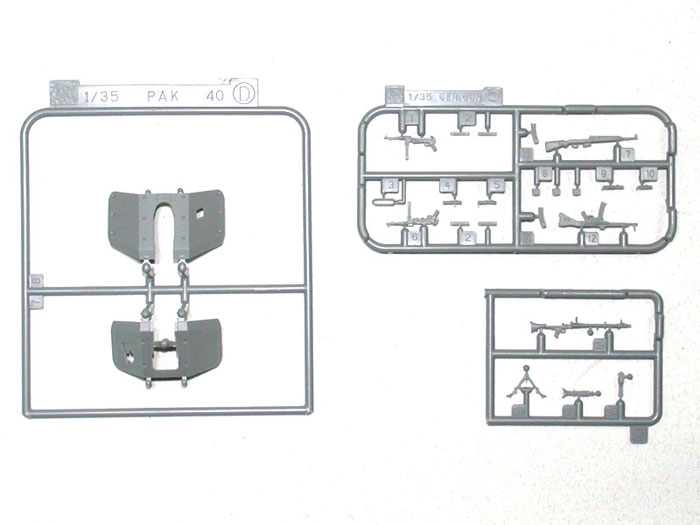
The 7.5cm Pak 40/2 is the same molding we have seen in DML’s earlier Pak 40 and Sd.Kfz.234/4 kits, which is to say that it is very nicely done. Options include showing the armored fairing over the front of the recuperator housing in either the closed or open position, though this would only be open during gun maintenance. The kit also provides alternate gun-sight mountings with the sight itself either mounted or absent. The overall level of detail is quite nice, and those who wish to refine it could use parts from Aber’s update set for the Marder III M to detail the gun breech, sight and fittings.
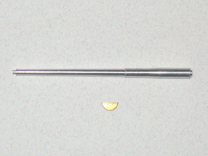
The gun comes with a choice of two-part styrene or turned aluminum barrels, and the aluminum barrel has slightly better detail definition. Both barrels appear to be approximately 4mm too long in the rear section when compared against the plans in the Armor Photogallery book, though I’m not entirely sure I trust these plans since they differ somewhat from Doyle’s plans in Panzer Tracts No.7-2. The Panzer Tracts book only provides a side elevation and no plan view of the Marder II. However, it does provide a plan view of the Marder III M and assuming the gun barrels are the same (the Marder III M mounted the Pak 40/3), the kit barrels measure correctly against these plans.
The kit provides a choice of three different styles of muzzle brake with separate inner baffle. All of the wartime photographs I was able to find show the second of the three options (parts B45/B55) though the preserved vehicle at Axvall mounts the first option (parts B46/B56). You also have the option of modeling the breech block open or closed.
The gun shield is molded in two parts with a separate etched brass part for the small elevating portion of the shield. The forthcoming CyberHobby update set will include pre-formed etched brass parts for the main gun shield, along with the bolts that separate the inner and outer shield halves.
Painting and Marking Options
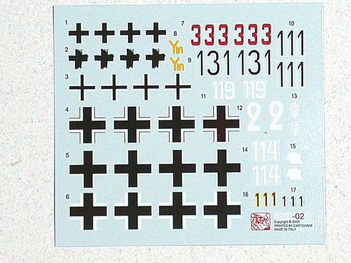
The kit decals are from Cartograph, and as usual are nicely printed and presented. Color schemes and markings are provided for eleven vehicles:
-
Unidentified unit, Eastern Front
1944 in dark yellow with soft-edged broad red brown and dark
green stripes. The vehicle carries no tactical number and
displays large balkenkruz on the superstructure sides and hull
rear.
-
Unidentified unit, Eastern Front
1943 in dark yellow with hard-edged red brown and dark green
patches. The vehicle carries the tactical number “333” in red
and displays large balkenkruz on the superstructure sides and
hull rear. This vehicle appears on page 26 of Concord’s
German Self-Propelled Guns.
-
Unidentified Unit, Russia 1943 in
dark yellow with broad red brown patches. This vehicle is
marked “111” in white-edged black numbers, with a smaller “1” in
yellow-edged black, forward of the large balkenkruz on the
superstructure sides. Another large balkenkruz is displayed on
the hull rear. See the notes for marking option #7 below.
-
10. Panzer Division, Tunisia 1943
in dark yellow with small dark green patches. This vehicle
carries no tactical number and displays small balkenkruz on the
superstructure sides and hull rear.
-
Unidentified Unit, Eastern Front
1943 in field grey with dark yellow over-painting. This vehicle
carries no markings apart from large balkenkruz on the
superstructure sides and hull rear.
-
Pz.Jg.Abt.49, Eastern Front 1944
in dark yellow with dark green and red brown stripes. This
vehicle carries the tactical number “119” in white on the upper
superstructure sides, and displays small balkenkruz on the upper
rear superstructure sides and the hull rear. Though the kit
instructions do not show a front view for painting and decaling
purposes, a number of vehicles from this unit displayed the
small balkenkruz on the left side of the driver’s front plate,
so check your references.
-
Unidentified Unit, Eastern Front
1944 in dark yellow with dark green and red brown stripes. This
vehicle carries the tactical number “111” with a smaller “1”
forward of the large balkenkruz on the superstructure sides.
This unusual marking begs the question whether this is the same
vehicle, or a successor in the same unit, as depicted in marking
option #1. Another large balkenkruz is displayed on the hull
rear. This appears to be the vehicle shown on page 52 of the
Armor PhotoGallery book and if so, it is actually an early
production vehicle with the welded reinforcement strips at the
rear of the superstructure sides. You should shave off the bolt
heads molded on the kit parts.
-
Unidentified Unit, France 1944 in
dark yellow with dark green and red brown patches. This vehicle
is marked “131” and displays large balkenkruz on the
superstructure sides and hull rear.
-
Panzer Korps “Grossdeutschland”,
East Prussia 1944-45 in dark yellow with small red brown
patches. This vehicle displays no tactical number, has small
balkenkruz on the lower rear superstructure sides and the hull
rear, and the “Grossdeutschland” divisional symbol on the right
hull rear.
-
Panzer Division, Hungary 1945 in
dark yellow with dark green and red brown stripes/ The vehicle
is marked “2” and displays small balkenkruz on the hull sides
(beneath the tools, so be prepared for decaling challenges) and
the divisional symbol on the left front of the superstructure.
- Unidentified Unit, Hungary 1945 in dark yellow with broad dark green and red brown stripes. This vehicle is marked “114” and displays small balkenkruz on the superstructure sides and the hull rear.
I am impressed with the wide number of marking options given, but I wonder at the lack of any options for the Sicilian and Italian campaigns. Numerous photographs exist of Marder IIs in action in Sicily, often crewed by Fallschirmjager troops, and this would have provided an interesting alternative to the mostly Eastern Front markings given in the kit. The aftermarket decal manufacturers will surely step in to fill this gap.
Click the thumbnails below to view larger images:
|
|
|||
Conclusion
In summary, this is an well-engineered kit that appears accurate in all major details. It is certainly up to the standard we have come to expect from DML. With care and patience, it will build into a very nice model.
The true purists will probably want to spend some additional dollars and hours to add the few missing details, but the majority of us will simply build it out of the box and be very happy with it.
I would hesitate to recommend the kit to younger or inexperienced modelers due to the large number of parts and the very “busy” instructions, but I highly recommend it to those with some prior modeling experience.
References
Armor PhotoGallery #9: Panzer Jaeger Marder II Sd.Kfz.131 by Wojciech J. Gawrych, Model Centrum Progres 2004. This book contains excellent photographic coverage of the late production Marder II at the Swedish Pansarmuseum at Axvall, along with the Pak 40 at the Panzermuseum at Munster. There are also 1/72 and 1/35 scale drawings and wartime photographs.
Tank Power Vol. I #209 Marder II by Zbigniew Borawski and Janusz Ledwoch, Wydawnictwo Militaria 2004. With text and captions in both English and Polish, this book contains a detailed production and operational history of both the Sd.Kfz.131 and Sd.Kfz.132 (the vehicle based on the Pz.Kpfw. II Ausf. D chassis and armed with the Russian 7.62cm Pak 36(r). Photographs are mostly wartime shots and provide a good deal of detail. There is also some coverage of the preserved vehicle at Axvall. While the book provides scale drawings, they lack the detail of those in the Armor Photogallery and Panzer Tracts books.
Panzer Tracts No.7-2 Panzerjaeger (7.62cm F.K.(r) ausf gp.Sfl. to Marder 38T) development and employment from 1941 to 1943 by Thomas L. Jentz and Hilary Louis Doyle, Panzer Tracts 2005. Pretty much the definitive pocket history of the Marder series, this book is packed full of details with production and operational history, technical details and some very nice photographs.
Armor At War Series 7022: German Self-Propelled Guns – Self-propelled artillery anti-tank and anti-aircraft guns by Gordon Rottman, Concord Publications 2005.
Achtung Panzer #7: Pz.Kpfw. I/II Series and Variants, Armor Graphix 1999 (?) Sorry but I don’t have author information and I’m not entirely sure of the year of publication.
Kit purchased with reviewer's funds
Home
![]() Discussion Groups
Discussion Groups
![]() Gallery
Gallery
![]() Articles
Articles
![]() Reviews
Reviews
Copyright
![]() Vendors Room
Vendors Room
![]() Links
Links
![]() Contact us
Contact us
Copyright www.missing-lynx.com 2006